September 4, 2004
After working on the panel and the radio stack wiring, I decided to start working on the E1’s gauge inputs, namely the fuel levels and volts.
Fuel levels were fairly straight forward once I’d figured out what happens to the signal through the sender and Van’s gauge (back up). Vans gauge outputs a 5v signal, and I use this for E1 too. BMA recommends the capacitance fuel senders for the RV’s, but since I have a quick build, there’s no chance to get the capacitance senders. Looks like crappy floats for me then!
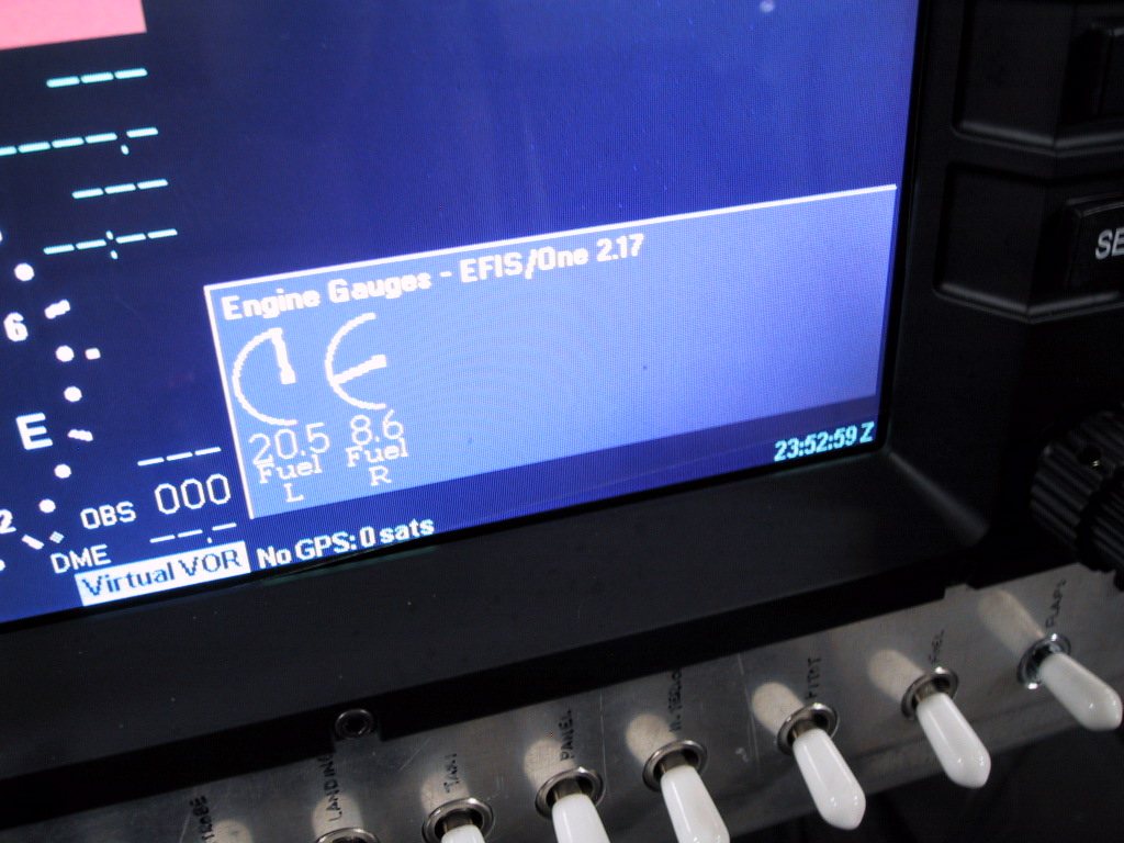
Calibration was easy. I double checked the outputs from the sender with my multimeter, and found it to be between 0v and 2.5v approx. So I made a cal table at certain points shown on the Van;s gauge. Now, this is only temporary, as when the wings go on, the calibration can be done properly by adding known quantities of fuel to the tank.
The Engine Gauges pop up when the senders show 0 gallons too! Sweet. There is a red area on the gauges, but it’s tough to see it with my lousy photography!
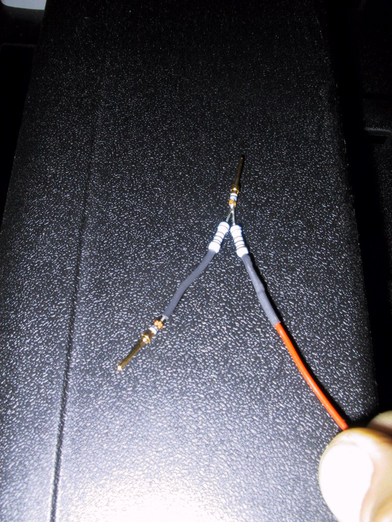
Next, I set about doing a voltmeter. Well, the book has an example of this, so again, it was fairly straight forward. I had to build a voltage divider for mine as the voltage input can only accept up to 10v (I think. Some later models can accept up to 30v!) So, here’s my voltage divider. Pretty easy really. Two 10K resistors…. I shrink wrapped the whole thing after taking this shot. It all fits inside the D-Sub plug shell for Analogue 2. Red wire is the input from the bus (protected by a 1 amp fuse) and the pin at the top is the voltage reading pin. Lower left pin is the ground.
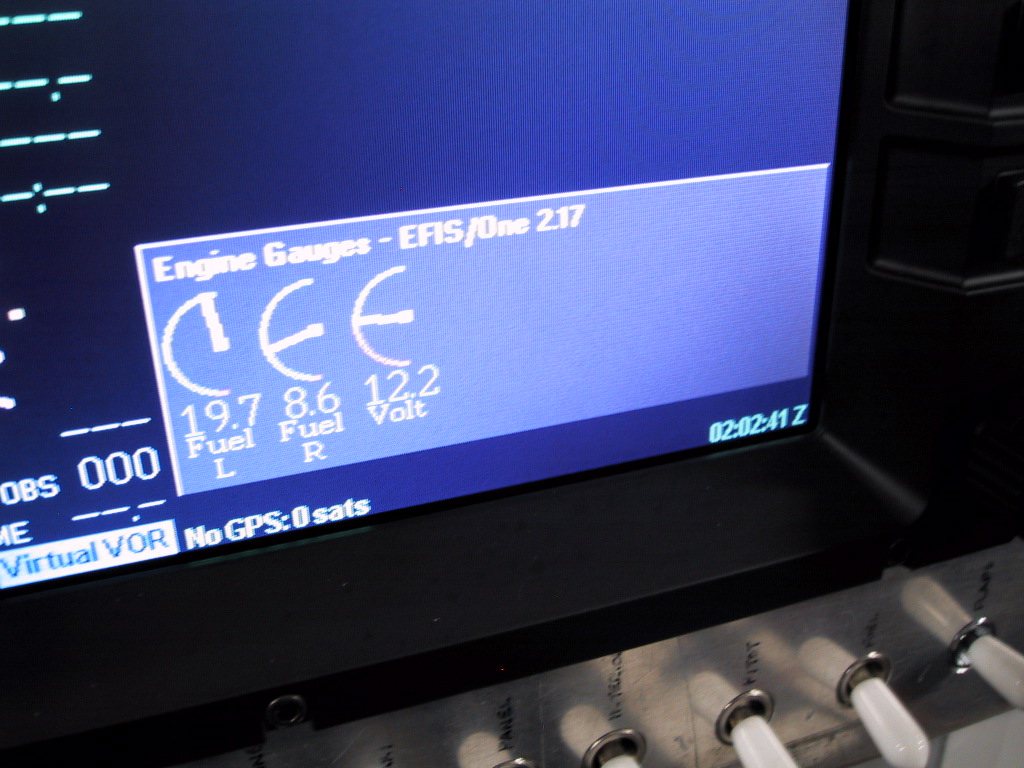
And, here it is in action. I’m running of my battery here, which is in turn being charged by a Battery Tender. So, only a measly 12.2v and dropping slowly since I’ve been sucking more out of it than the charger can replace! Sorry about the lousy photo.