About the Blue Mountain EFIS/1
Still in it’s infancy, the EFIS1 held lots of promise. Back then, it was housed in a plastic box and was pretty much hand made. We discussed whether this was a viable option, and put down our deposit. Several months passed by, lots of development went on. It was ready before we were really, but if it’s ready, we’ll take it!
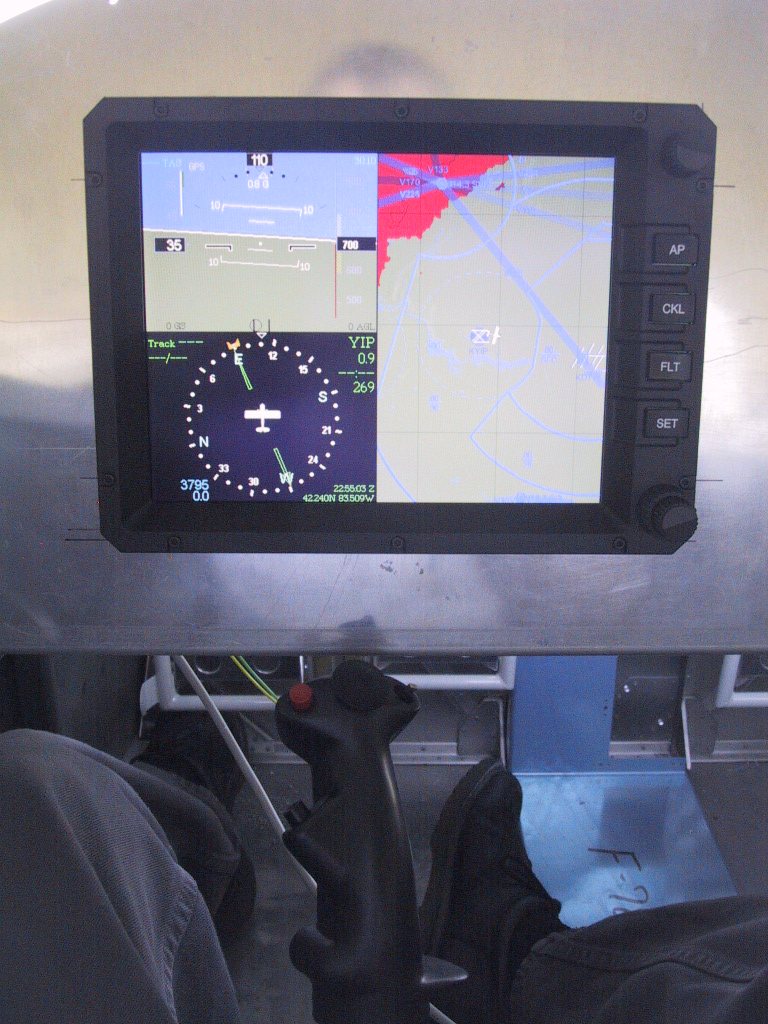
Below are some screenshots of the E1. The display is nothing short of awesome. The terrain mapping resolution has to be seen to be believed. Take a look at the Guided Tour on the Blue Mountain Avionics website. Pretty slick stuff.
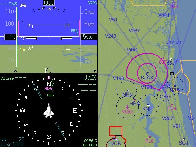
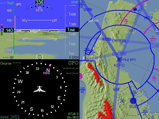
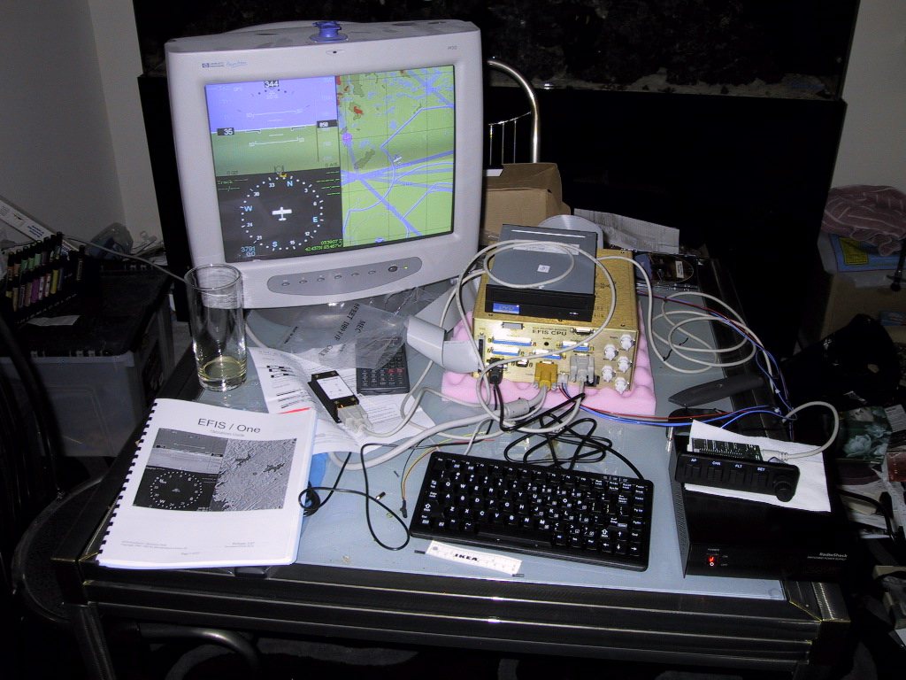
We opted for the internal flash memory (now standard), and the digital autopilot. The Blue Mountain site shows this in greater detail than I could ever hope to here. Below you can see the E1 fired up for the first time at home. The VFR airways shown are converging on the Salem VOR. Keyboard is used for setup, and the DVD is used for updates only, although Greg announced at Sun n’ Fun this year that downloadable updates are coming soon. This stuff just keeps getting better.
Our whole panel revolves around this display. I made sure that it was positioned perfectly for the pilot. Everything else can be worked around to suit. See our panel plans to see what was going on during all this time with the design!
Our autopilot servos are mounted aft for the elevator, and attaches to the elevator bellcrank by the baggage bulkhead. The roll servo will be out in the starboard wing, connected to the aileron bellcrank. Since I haven’t done too much with our QB wings yet, I haven’t got to a point where I have pictures to post.
Here is the first time I fired it up at the hangar. We’re almost a mile from the airport reference for YIP! Salem VOR is at the top left. Michigan is pretty darn flat, but if I mess with the altimeter setting, I can make some of the terrain show up red, meaning it’s higher than us, and we may hit it! Not now we won’t! This baby ain’t going anywhere for a while yet!
I contemplated long and hard about how to mount the CPU. Originally, they were being mounted on shock mounts. Later on, this was found to reduce the accuracy of the autopilot, so solid mounting was called for. CPU has to be in level flight attitude. Our support tray is hinged of the upper firewall angle, and attaches under the sub panel via some leveling screws.
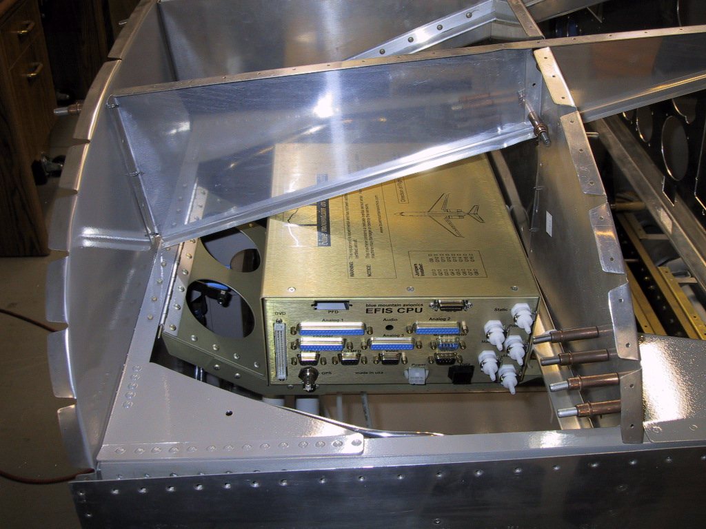
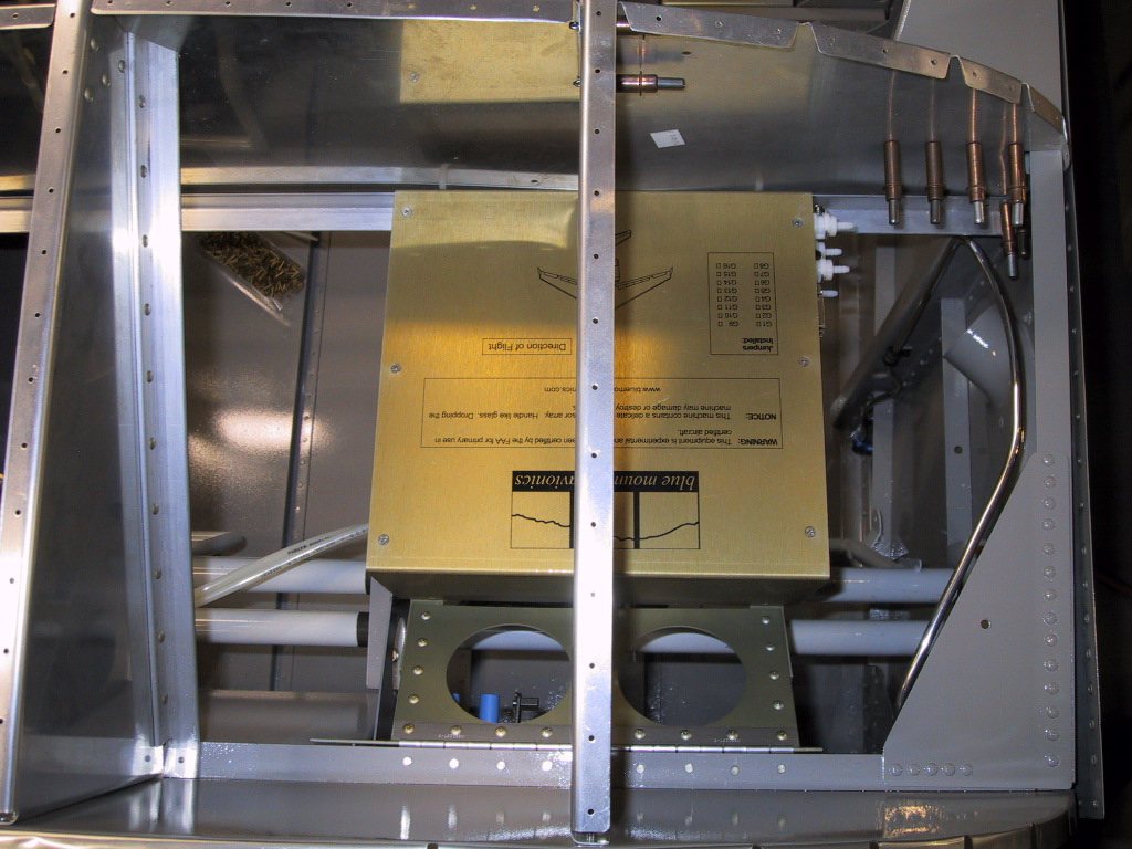
Here, the leveling screws are actually tie wraps! Just temporary you understand. The whole tray swings down, so we’re able to remove the unit if necessary for future upgrades.
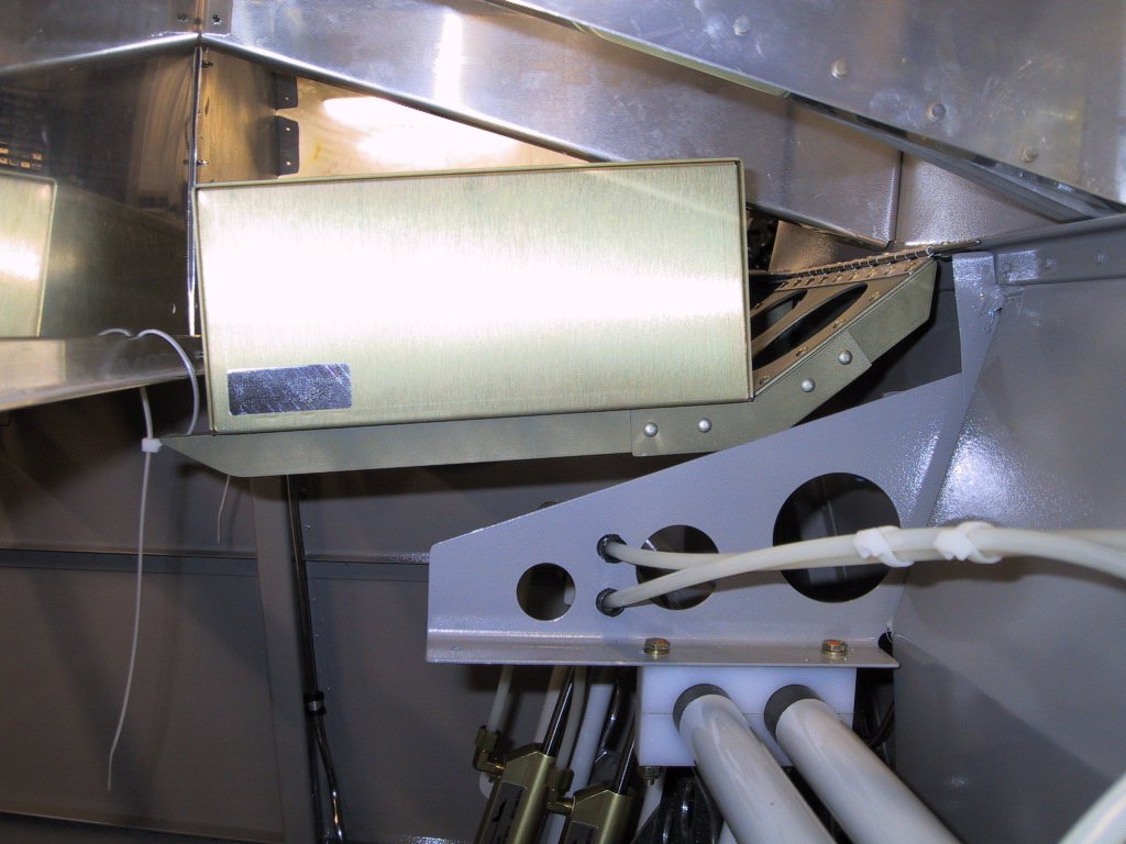
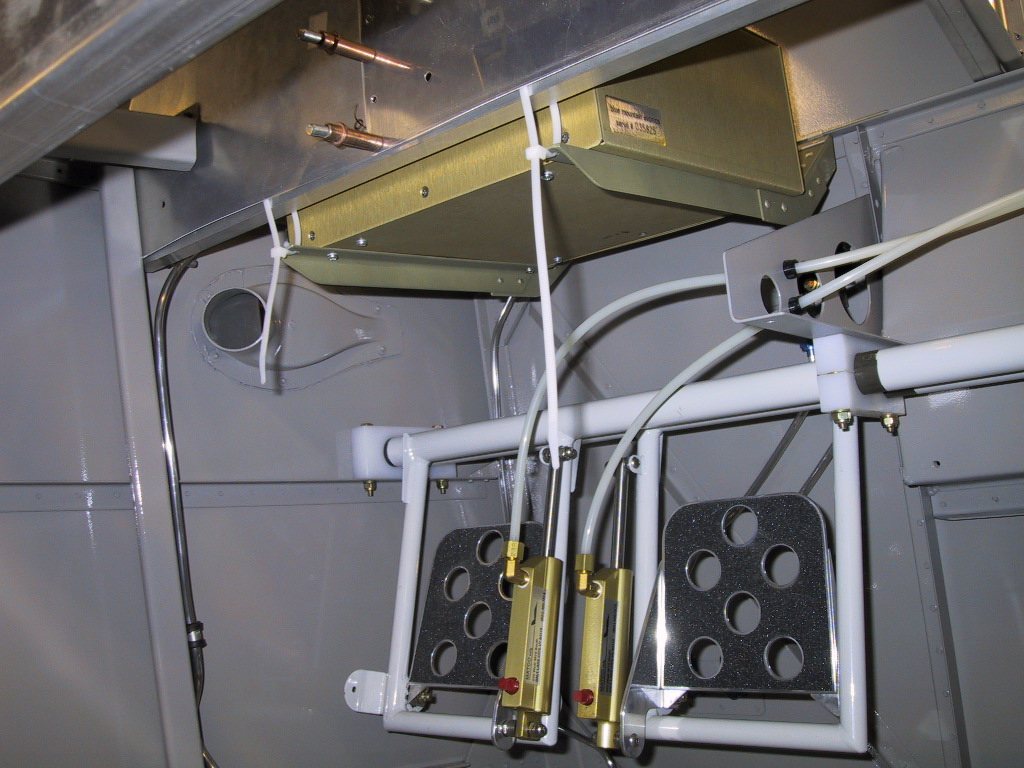
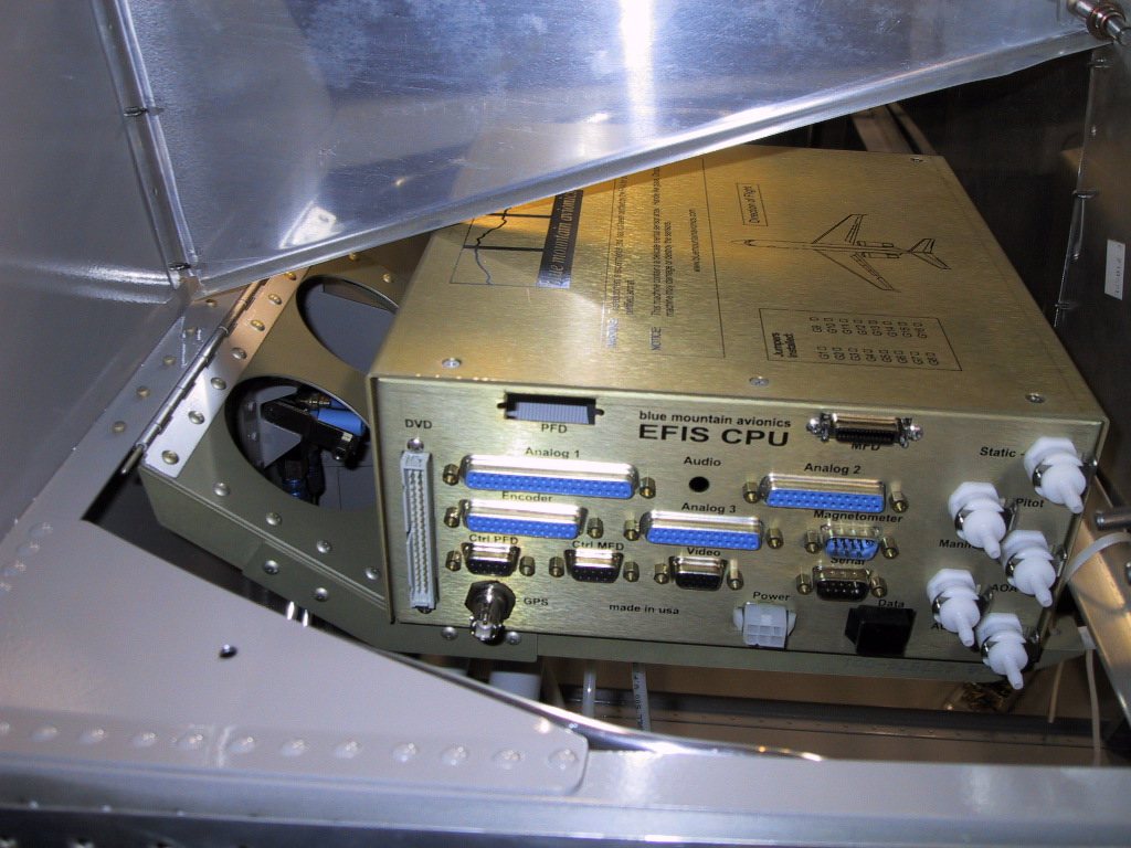
Fabricated the brackets. Now the screw are in place. Once I’ve established level, I’ll make spacers to hold the whole thing rigid.
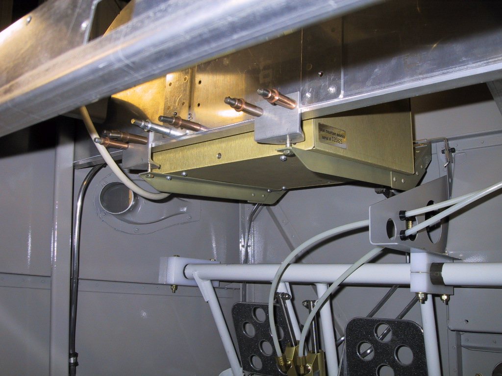
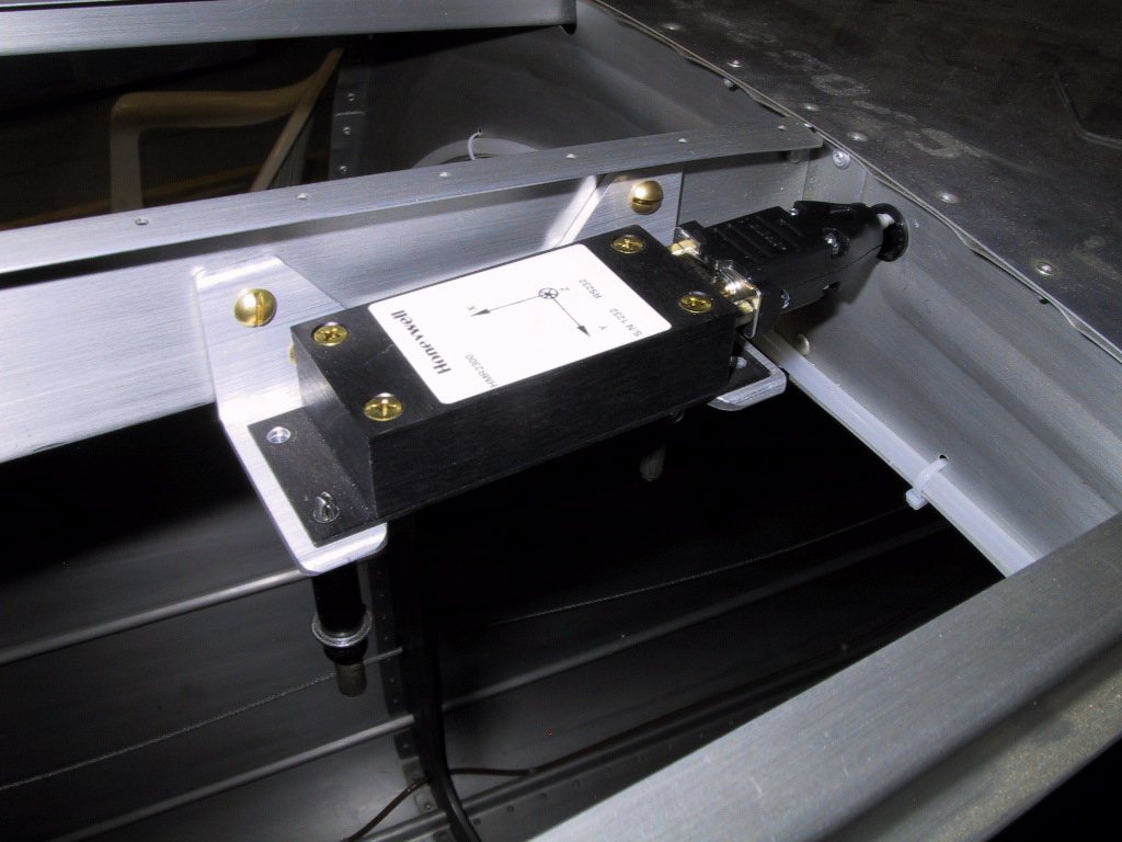
Magnetometer support bracket… A little over engineered? Note the brass screws… No ferrous materials allowed.
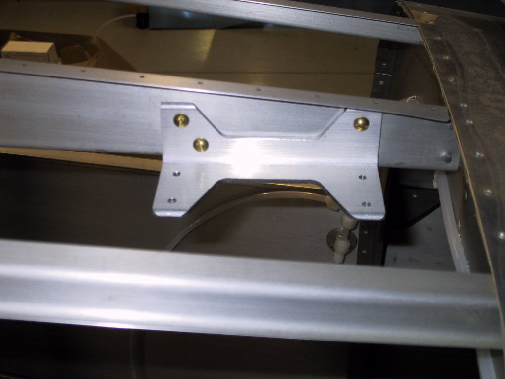
Here the autopilot controller is mounted to the subpanel just behind the CPU and in front of the display. The display is pretty slimline, so plenty of room back here for stuff. The round piece that is sticking out is actually the altimeter.
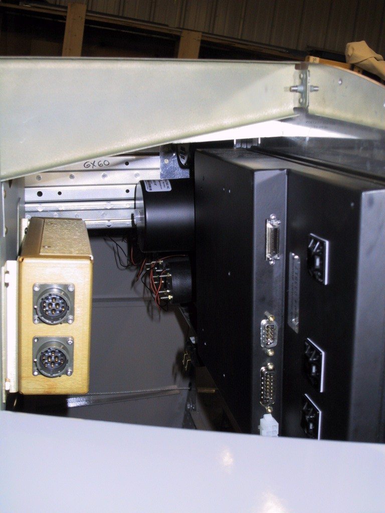
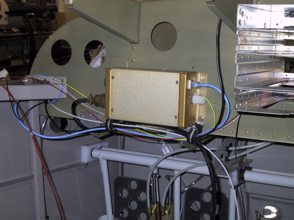
Here I’ve started wiring the autopilot controller. I made a crossover cable to go between the CPU and the controller, since I only needed it to be a couple of feet long.
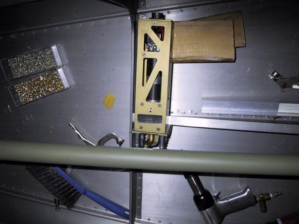
This is the elevator autopilot servo. I partially borrowed the idea for mounting this from Dave Nickolson and his RV-9A. Thanks Dave! His installation pictures can be seen on the BMA Discussion Board here. Do you like my outboard supports made from scrap shipping crate?!
Also, it’s kind of hard to see in this shot, but I ended up reinforcing the connection between the rib that the servo bracket is mounted too and the bulkhead. The rib had a tendency to pull away from the bulkhead, which I wasn’t happy about. I just used some 3/4"x3/4"x0.063" angle.
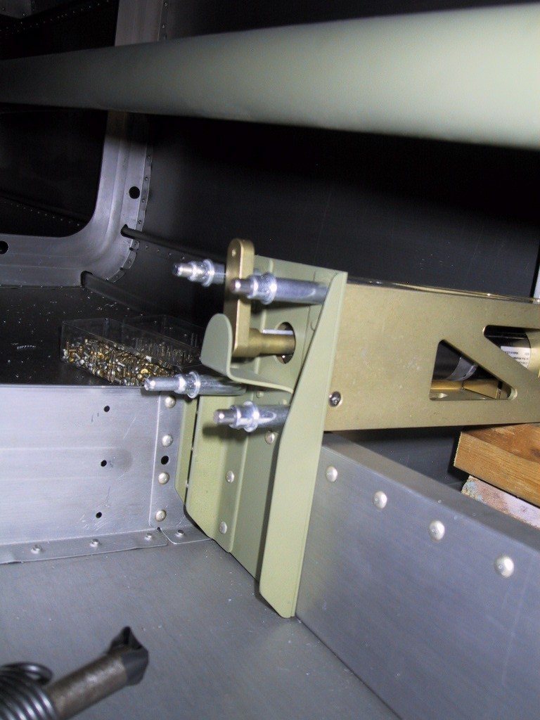
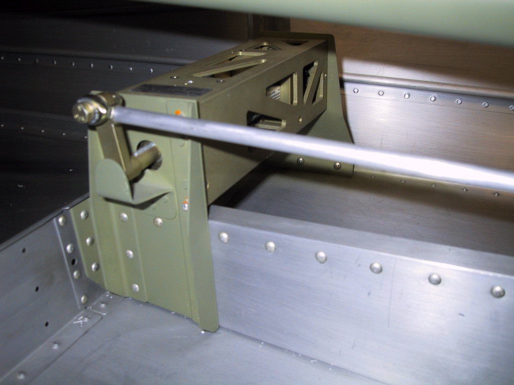
The little tab that covers the output shaft is there in case something comes loose. It will prevent the arm from coming of the shaft. Hopefully, this little puppy will never be used.
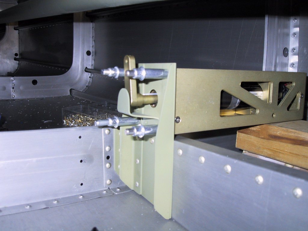
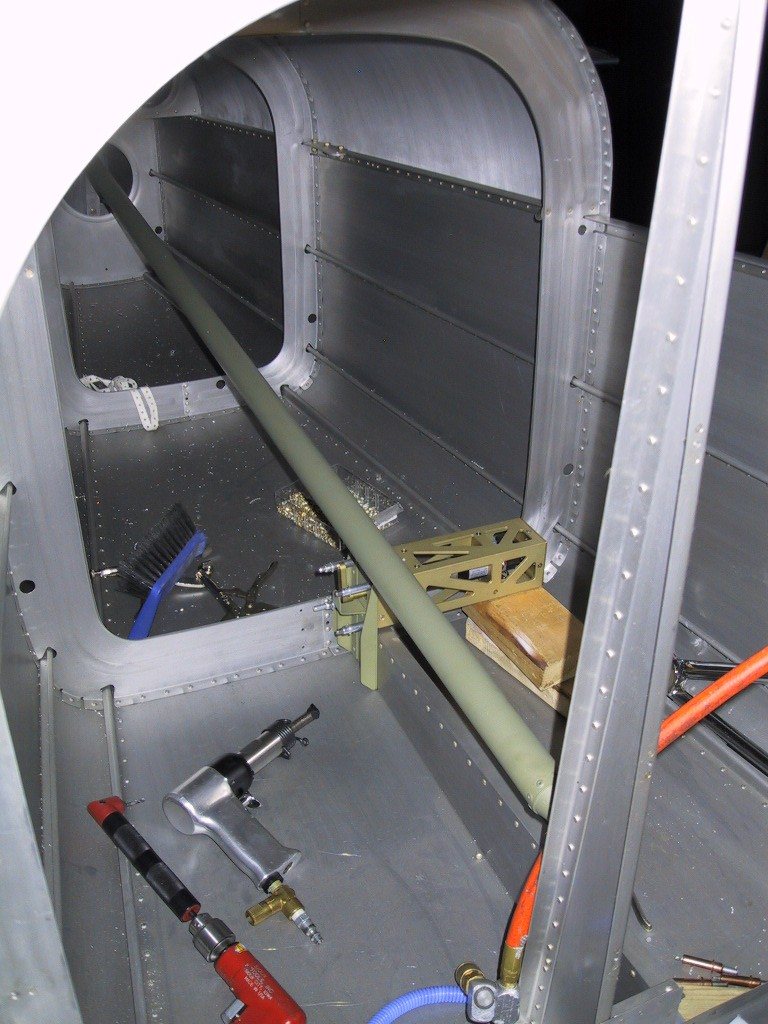
I did finally get around to replacing that wood with some metal! All this is removable for service should the need arise.
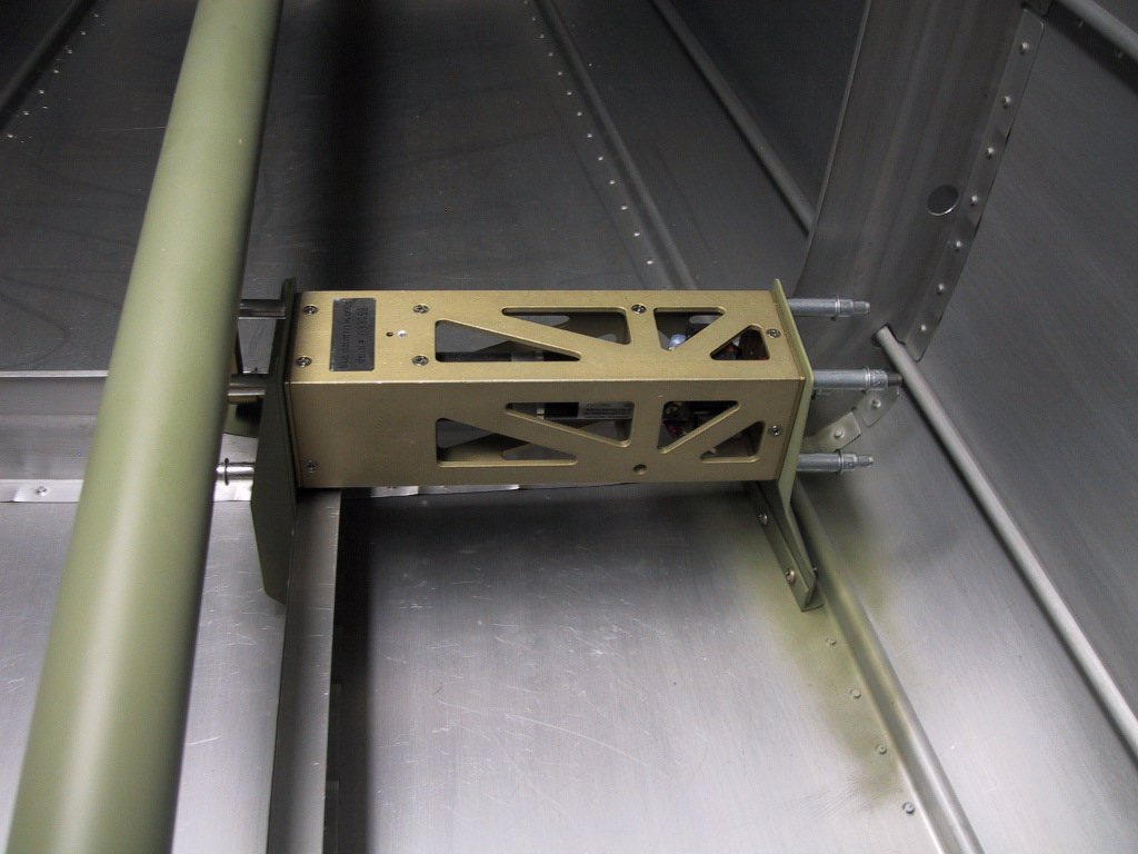
I got hold of some dinky little MIL spec socket screws to mount the servo properly. I’ve tugged on this as hard as I could, and it ain’t going anywhere!
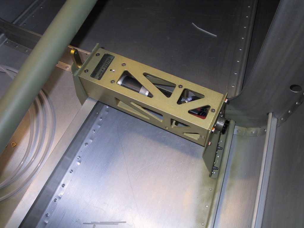
I got around to wiring the magnetometer in too. I made my own cable from three conductor shielded, and used the shield as the ground conductor. Works too, since the HSI on the EFIS1 paints numbers! I went around the block on this trying to get an all plastic 9 pin D-Sub. I found one, but then there wasn’t a means of positively attaching it to the magnetometer. In the end I ended up using a regular crimp type D-Sub connector.