


November 7, 2005
After getting back from the hoby and electronics stores, I finished the flap position sensor installation and then set about more electrical stuff.
I sometimes get messed up with what pages to put this stuff on. Is this electrical? Yes… Is it fuselage? Yes… So, I don’t know.. I’ll document it here today!
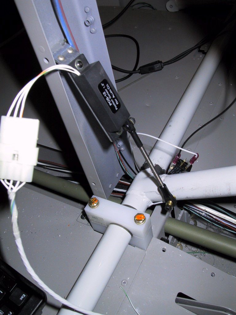
I bought some 6-32 size rod end bearings from the hobby shop to complete the flap position sensor. I joint at the sensor end of the rod was tightened without the ball in there and filled with epoxy to set it rigid. This is because the sensor is hinged at the top for easy removal, and if there are three pivots, it’ll just flop all over and never work. He it is in the down position… Looks like the up position? Well, here it is, but at the flaps, it’s down.
And the up position….
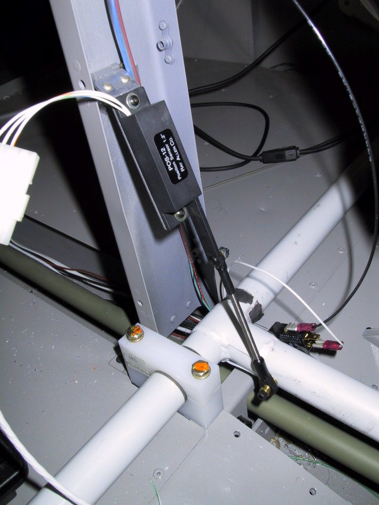
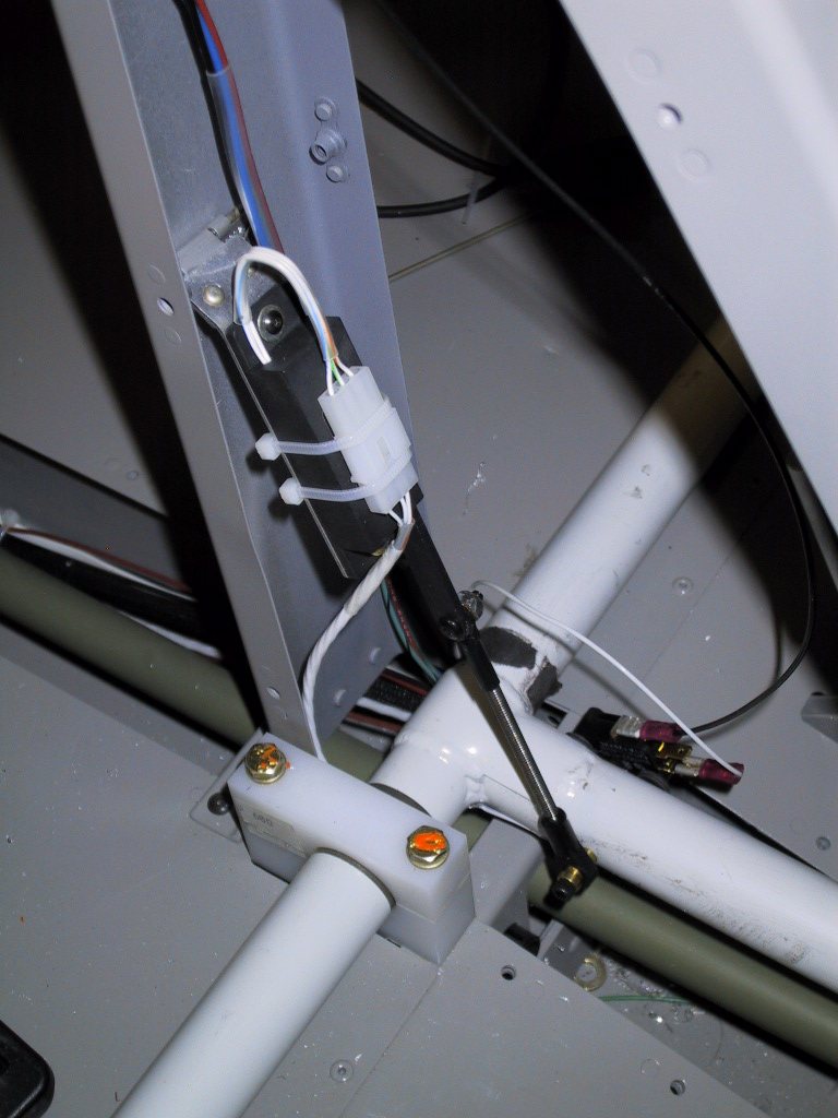
As you can see, I have a five way connector on there in the above pics. While I was at the electronics store, I bought some three way ones, so I decided to replace this one and fix my wire routing. I also put some heat shrink for strain relief on the AOA flap switch wires after I took this photo.
Time to move forward… In the cabin, and figuratively. Two things that needed doing were the fuel flow sensor, and the fuel pump. I got the fuel flow sensor wired to the EFIS One’s Analogue 2 ports. Pin 6 was 12v, Pin 19 was ground, and Pin 7 was the pulse sensor channel. This was pretty easy, but I’ve not set up the sensor in the E1 yet. The box is still out on the bench so I can get some access around the back of the firewall.
This is the fuel sensor end. Once again, the Molex plugs come in real handy.all these wires look a bit of a mess right now, but they’ll all be tucked away inside the centre console when it’s finally installed some time soon.
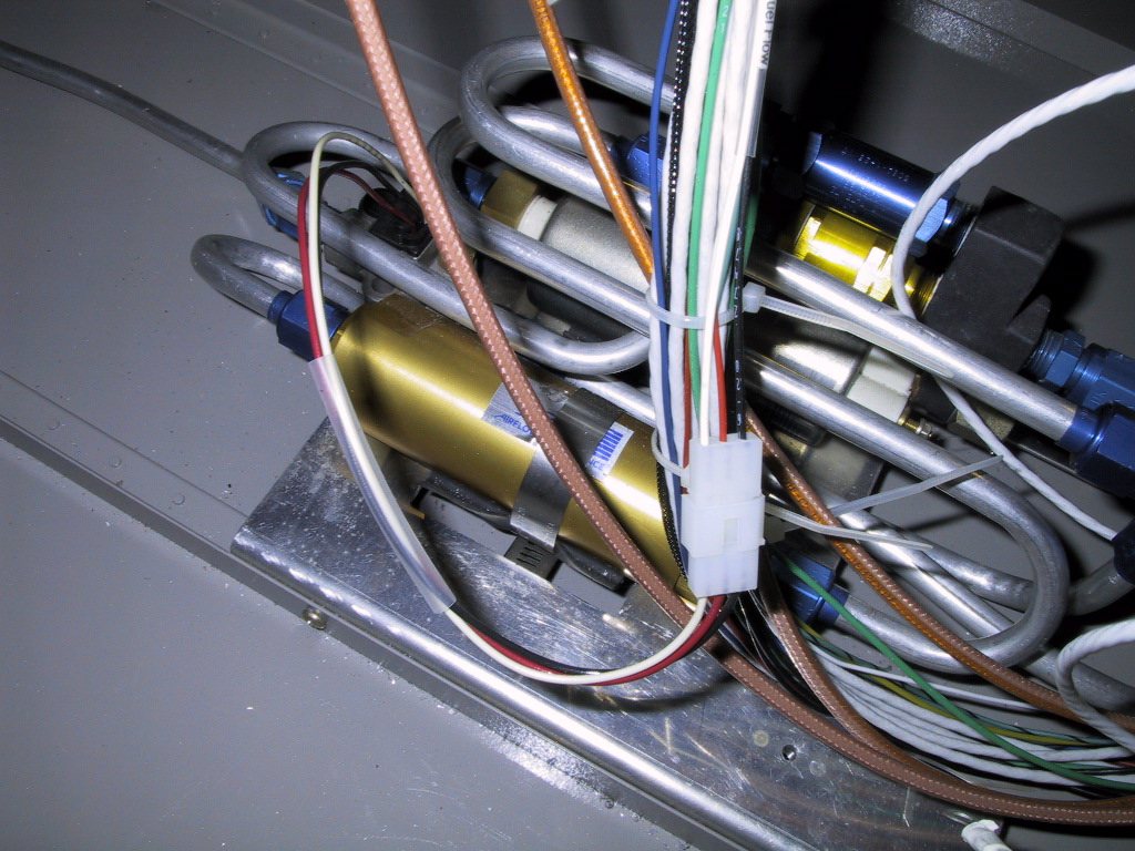
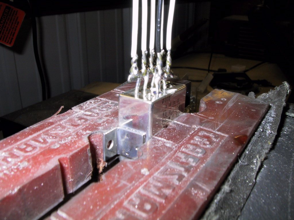
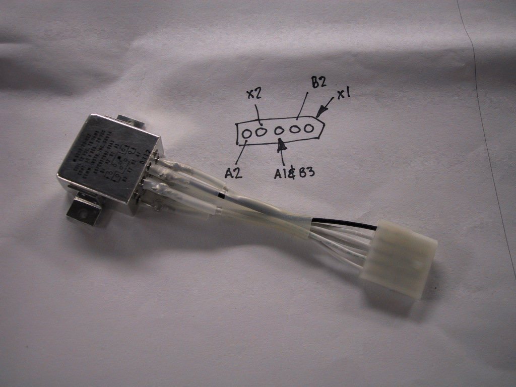
The fuel pump has this really strange relay that operates it. There are little hooks on it that you loop a wire on and solder. So, here I decided a pigtail was the way to go. Again, Molex connector. I got away with a five way here, and to pins are connected together that go to the fuel pump +ve terminal.
The completed unit. I drew a diagram on the FADEC wiring diagram of the connector pin outs. X1 is the black wire.
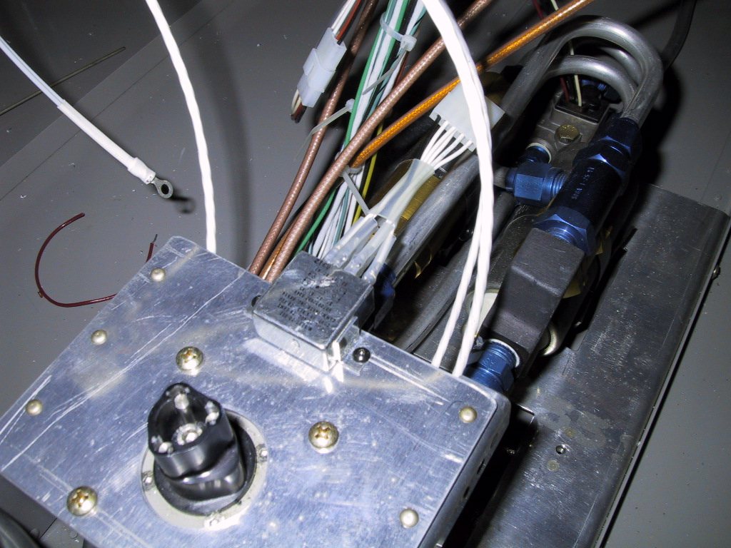
A great place to mount this thing turned out to be right by the fuel selector. Hopefully, there won’t be any vapours leaking around here for this relay to spark up! Actually, this relay is sealed. I bet this is the reason why!
On Wednesday, I’ll finish this off, and run the wires to the wing roots for the nav, landing and taxi lights. Once these are in, I think the wiring is finished aft of the panel. Ahead of the panel, I have to run the alternator switch wires, and that’s about it. I’m almost there.