Our electrical system
Our electrical scheme will follow Bob’s AeroElectric scheme Z-12 more or less. We aim to have dual alternators due to the fact that this will be an all electric plane. I’m one of those that thinks vacuum systems suck (I know… old joke).
At first I was a little daunted at the prospect of wiring our plane, but one wire at a time is what Mike said, and sure enough, he’s right. Eventually, it all comes together and hopefully it doesn’t smoke the hangar out when I flip the switch. I’ve been cheating though by turning things on as I’m going along just to make sure!
I’ve been getting most of my stuff from Stein Bruch at SteinAir. His prices are excellent, and stuff always arrives promptly. I even got a free T-Shirt once. It was a big order though.
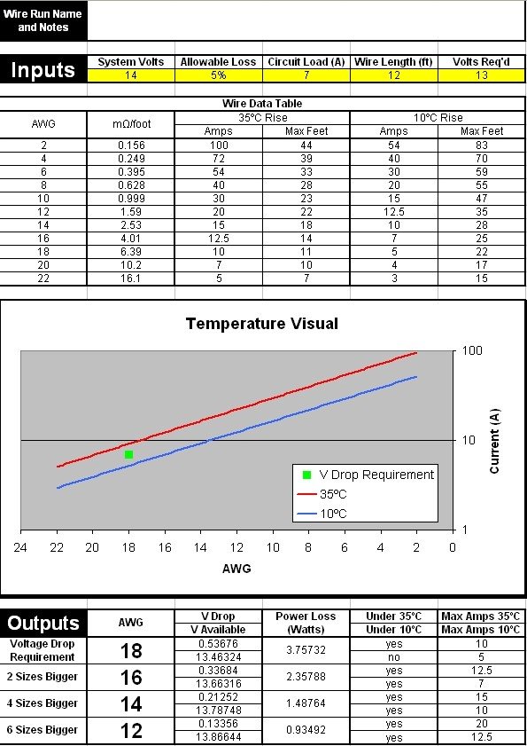
I made an Excel sheet to calculate wire sizes based on equations and charts in the AeroElectric book. I’ll post it here, but be aware that I’m not an Electrical Engineer, so if you use it and spot a problem, be sure to let me know!
Basically, the inputs are along the top in the yellow boxes. Everything else is calculated based on the Wire Data Table. At the bottom are the results by wire size. I only plotted the voltage drop requirement size, because plotting the other sizes would cause problems thanks to extrapolating data.
I have this on my PDA, so down the hangar I can plug in the numbers and save it off. Then when I get home, I can print it off and add it to my electrical system folder.
Click the image for the Excel tool.
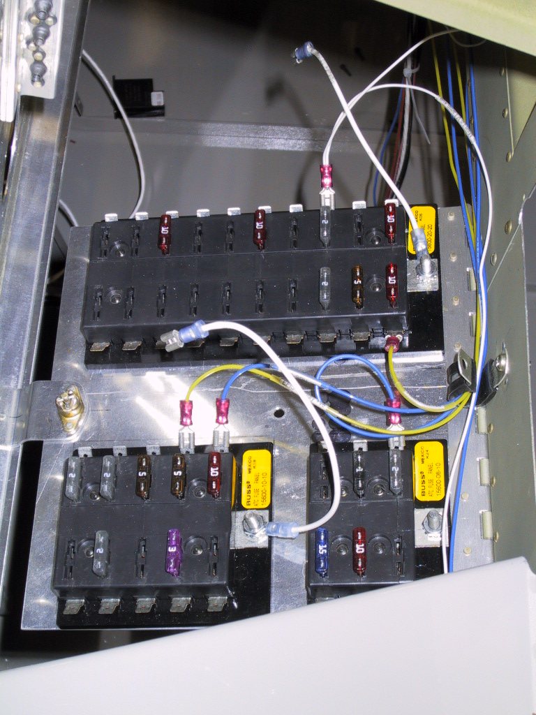
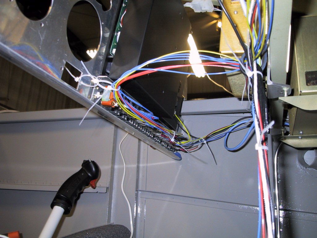
Reading the AeroElectric Connection, the fuseblock idea made sense to me, so this is the direction I’ve been heading. The only circuit breakers will be for the alternators. You can see here the main bus top, essential bus lower left and the battery bus lower right. This whole ensemble swings down for access once it’s all together. I haven’t even got half of it wired yet, it’s taking me forever!
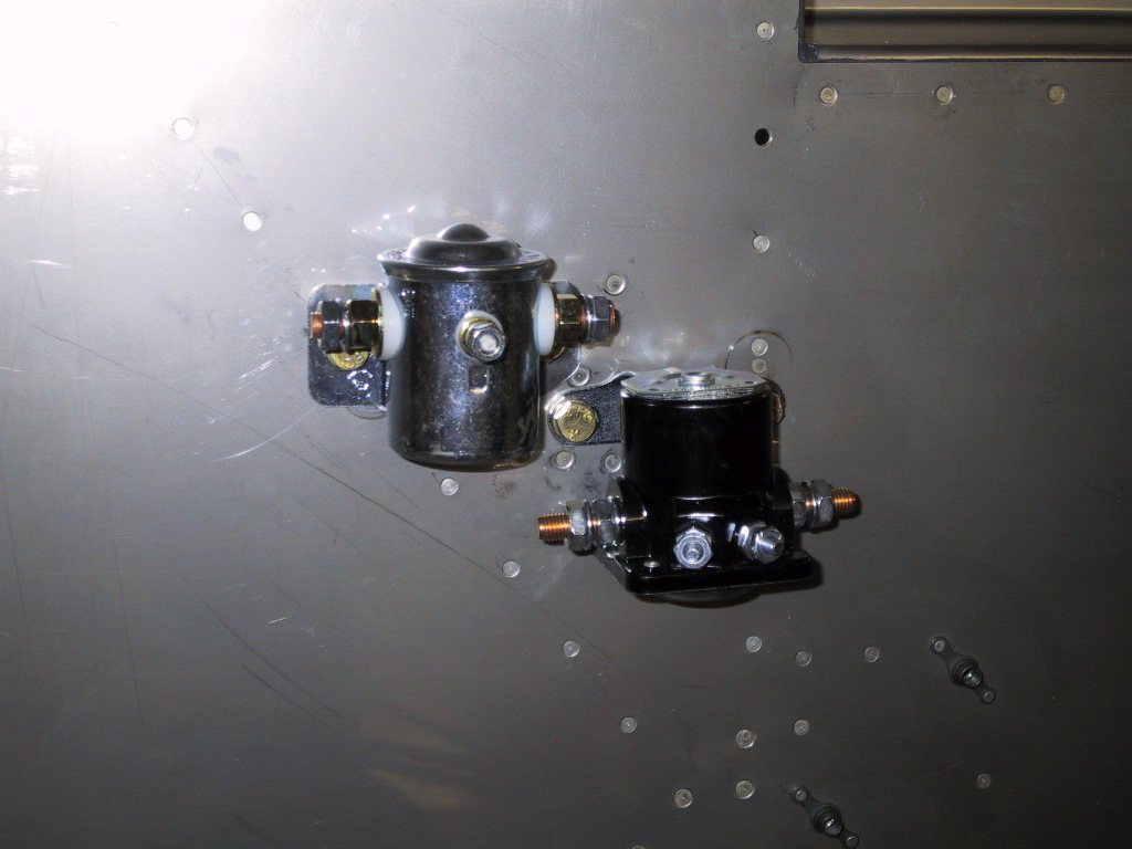
Here’s the battery and starter contactors. Not wired them as of yet. I need to make the diodes still.
Here’s a gratuitous shot of the switches and some of the wiring. Lot’s of temporary tie wraps to help keep it where I want it. Otherwise, this would be a mess of spaghetti!
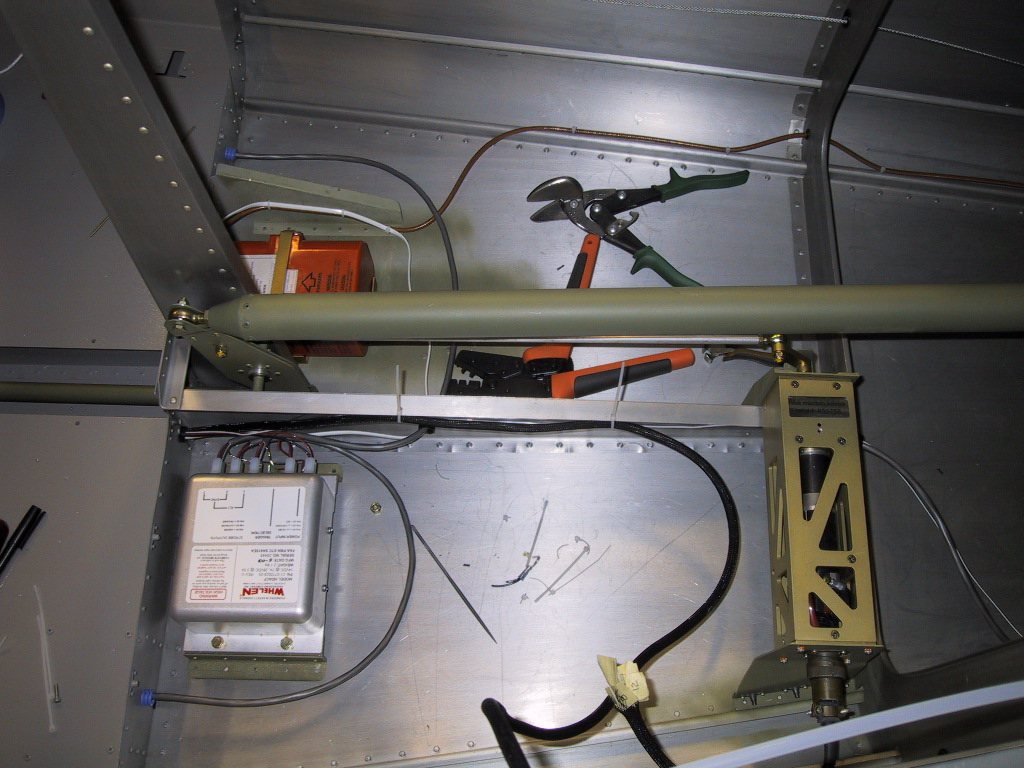
This shows the installation of the ELT, Strobe PSU and the A/P servo. The A/P servo cable had to be cut in order to thread it through my fuselage. I also took the liberty of shortening it some. I spliced it all together, heatshrinked it and put some insulation tape on it. The tape I used is the type used in the auto industry on harnesses. It’s pretty good stuff, and will last a LONG time (I got it off Mike… Thanks Mike!). I ran conduit under the left and right floorboards for the noisy strobe cables to try to keep it away from the rest of the electrical system and antenna cables.
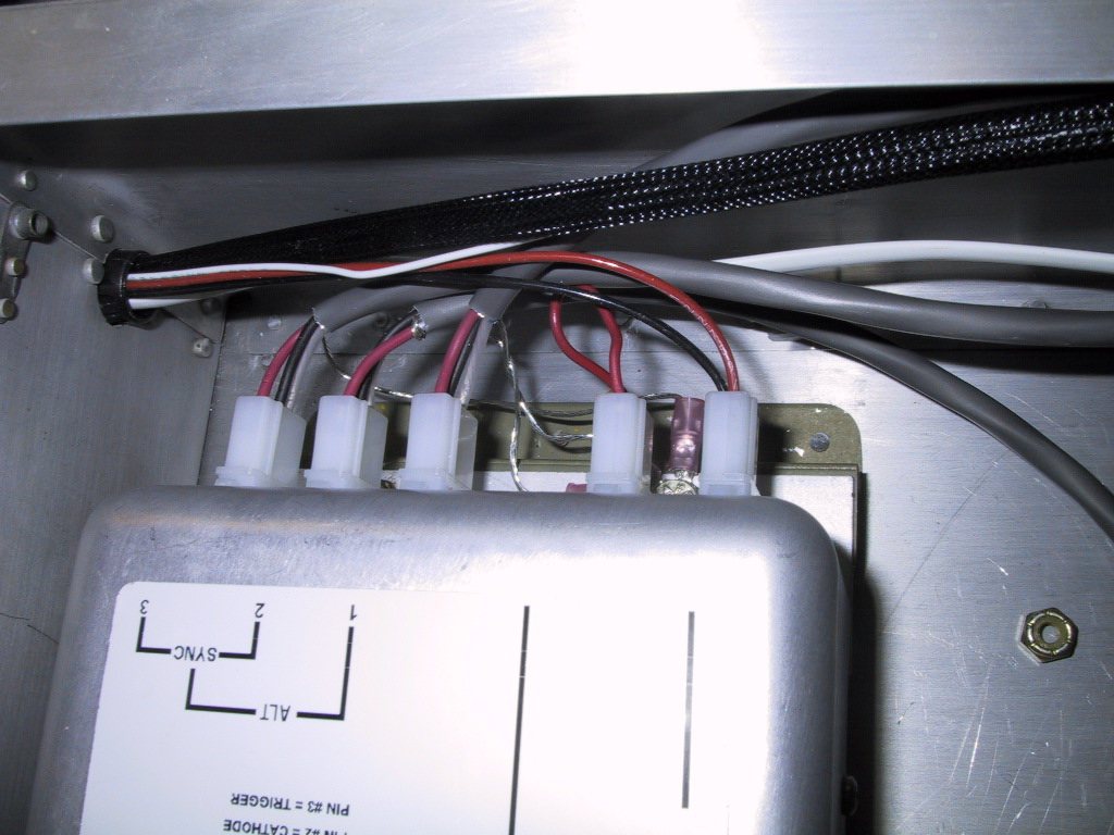
A close up of the strobe wiring. The shields are connected to one of the mounting bolts for ground. The ground for the actual PSU runs all the way forward to the ground block on the firewall/panel.
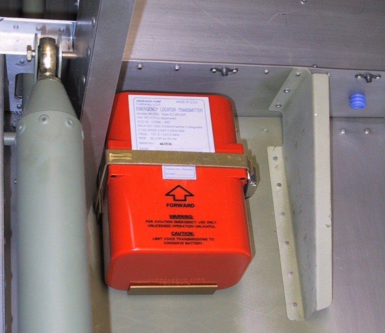
A close up the ELT. I put a rib in there because after mounting the holder to the floor, it felt a little too flimsy. The rib helped quite a lot. I don’t want this thing going off every time I land due to bouncing around on a flexing belly skin!
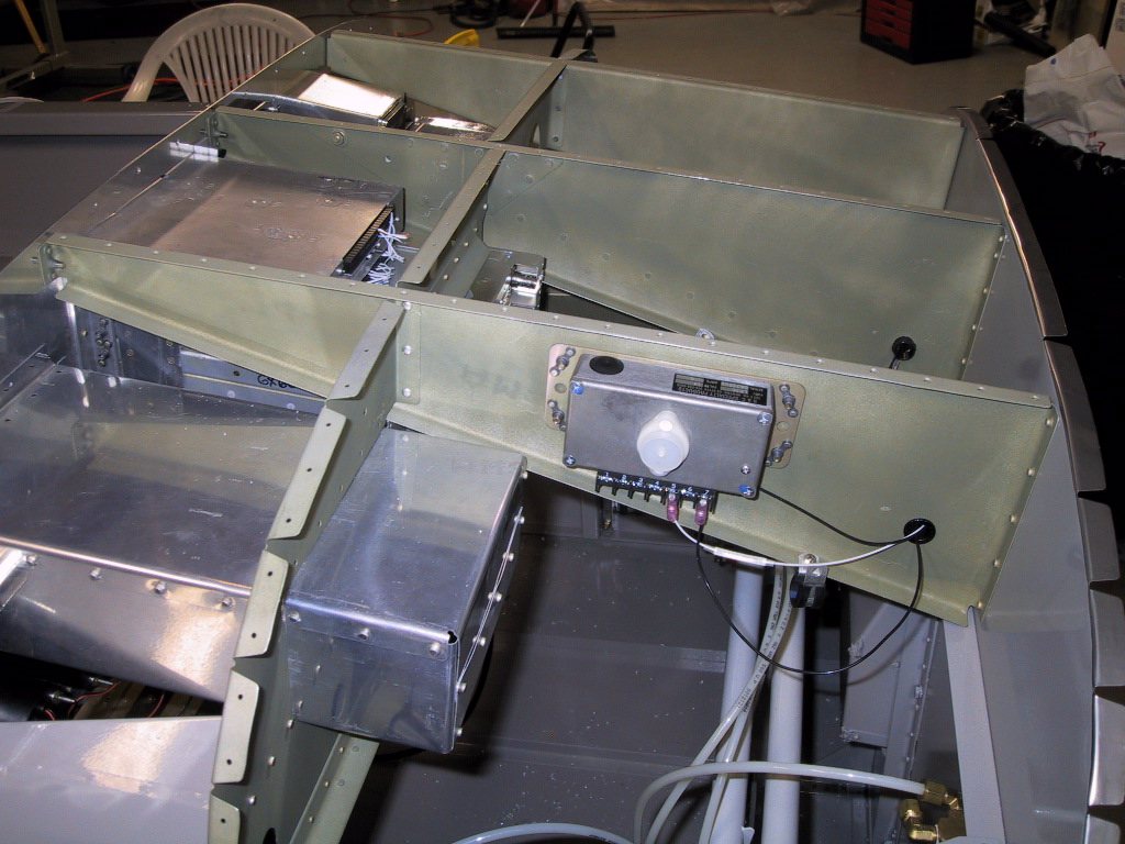
Here’s the regulator from B&C. I need to get another standby one too, which I’ll mount in the same place, but on the other side of the rib. That way, the regulators will form a nice rib sandwich!
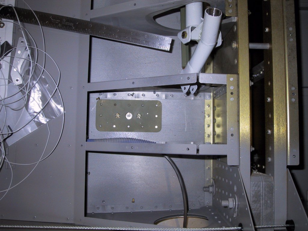
The doubler plate for the transponder antenna. Mike’s friend Russ was in town, and he helped me rivet this. Russ is building a Rocket.
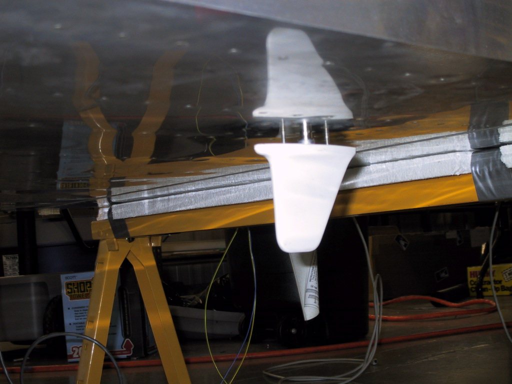
The transponder antenna. It’s just hanging there for now.
Most recently, I’ve been working on the flap system. I got the whole lot in OK, and also mounted some bulb holders underneath the cross bar that supports the seat backs for interior baggage area illumination. I’ll try to get a shot of it next time I’m at the hangar.
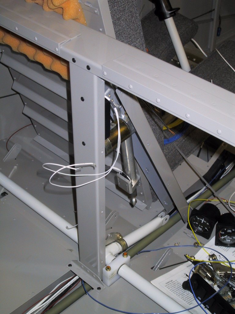
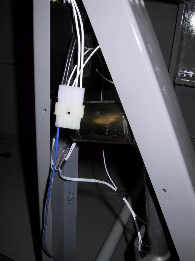
Here is the connector for the flap positioning system. I’m getting to like the Molex connectors. They lock together positively, and you can get them in many different configurations. Here, it also serves the purpose of connecting the interior lamp wiring (the blue wire coming up).
The flap positioning system has four wires to connect. No need for relays either, which is great for our Infinity stick grip mini toggle switches. There are four wires to connect… +ve, ground, extend and retract. I’m now working on the stick grip wiring, so I can finish the flap stuff off.
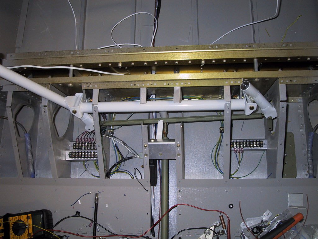
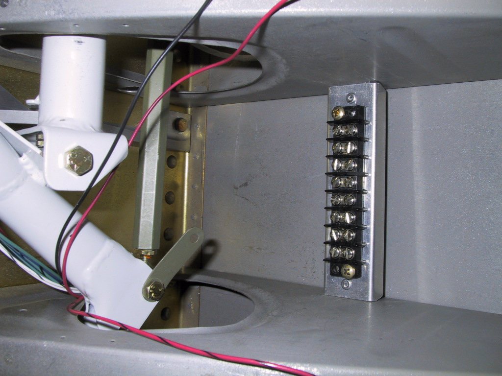
Here you can see the beginning of the stick grip wiring. I made some support channels for each strip. They turned out OK. Unfortunately, it’s not so easy to get terminal strips with enough terminals for the Infinity grips, there are so many functions. I am able to combine a lot of grounds, but not all of them, since I’m running governors from Matronics for the trim system, and the flap position system from van’s. These have a funky set up as far as grounds, so need to adhere to the circuit diagrams supplied!
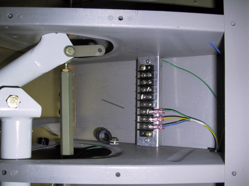
Here I figured out which wires were which for the aileron trim. I had terminals on the right hand side, and then remembered I needed to link in the passenger side grip too! Duh! So, I ended up cutting these off and re-crimping with another wire in there for the cross link.
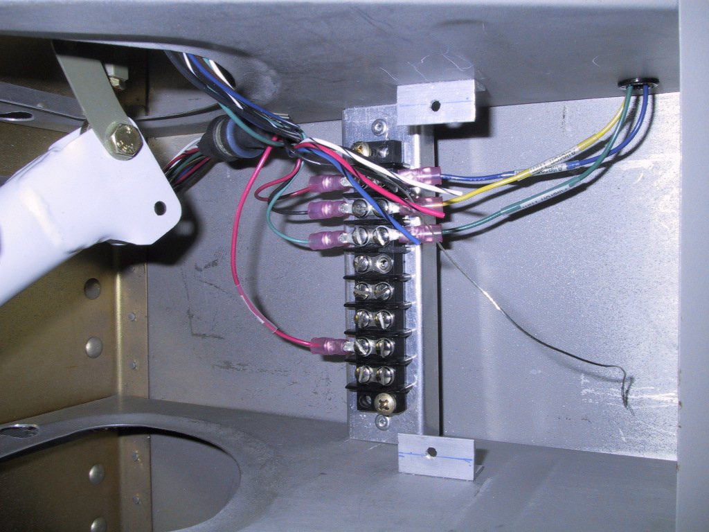
Et voila! Here it is in better shape. the lower blue yellow green wires are for the elevator trim. The governors are mounted under the seat floor, with a small hole in each floor to adjust the speed. There’s a heck of a lot of wiring going on here.
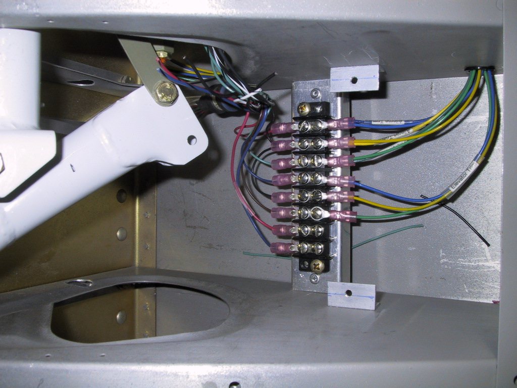
Here’s the co-pilot side, showing the aileron trim. The cool thing about the Matronics governors is that if a trim is activated by either pilot or co-pilot, it locks the other guy out, so a short circuit cannot occur. Sweet.
So, I spent 9 hours bent over this thing today doing the stick grip wiring, and my back is killing me. It still isn’t finished, and it doesn’t seem like I’ve done very much really. If you look hard at the pilot side seat surface, there’s a little hole between the left centre rib that forms the tunnel, and the next rib to the left. This is where the governor is located. Easy adjust, without having to take anything apart. I’ll stick a label on this panel so I remember which way to turn the potentiometer.