Planning the panel
Instrument panels seem to be one of the biggest attractions for scrutinisation of everything on an aircraft. Some are basic, some complex. Some look like someone took out a shotgun, stood back, blasted some holes, and filled them with a random set of instruments. Most are limited by budget, and man, how it can all add up is nothing short of amazing.
Over the life of the project, our panel design has gone through several iterations, in order to find a balance of functionality and simplicity. We wanted our plane to be capable of serious IFR, so we had to pack it full of stuff…. Or did we?
While at Sun n’ Fun in April 2002, we ran into the Blue Mountain Avionics stand, and what we saw was nothing short of amazing. Still in it’s infancy, the EFIS1 held lots of promise. I have decided to dedicate a page of this site to the EFIS1 and it’s installation as it progresses. So far, things are looking great. So, the secret’s out. We went EFIS1, had some back up steam gauges and an Apollo stack. Good to go. Here are the evolving developments….
It’s amazing looking at peoples first attempts at an instrument panel. Just take a look at some of the websites out there. Big plans, over complicated, slapdash, and above all EXPENSIVE! Ours was no different! I’m sure when we all open up EPanelbuilder.com for the first time, we’re overwhelmed by all the things we can put on there. So, that’s what we do. Gung ho! Here’s the first one! It’s awful!
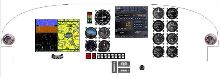
To be completely honest, it hasn’t changed all that much so far as content. It has changed layout considerably. This panel originally had the first Blue Mountain EFIS1 display, which was considerably different to the one that currently ships. As time progressed, the Blue Mountain display changed it’s form factor, and this in turn prompted a rethink. I think it was about this point I decided we would probably need to add some to the bottom of the panel based on the display’s dimensions and the RV’s panel depth. I’ve seen plenty of RV’s with panel extensions on them, so we’d find a way to accommodate it all.
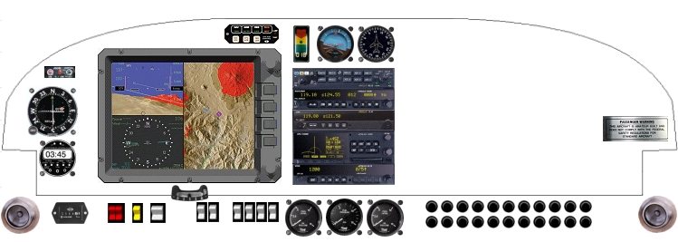
So now we have a new display, a few less back up engine instruments, and no more airspeed indicator, in favour of using the AOA. The GPS would also show groundspeed, so we were good to go….. Then I started getting greedy again when BMA announced they could support two displays! Will it ever end?! It’s looking a little to much again! Airspeed indicator is back after much to-ing and fro-ing and fretting about what to have and what not to have!
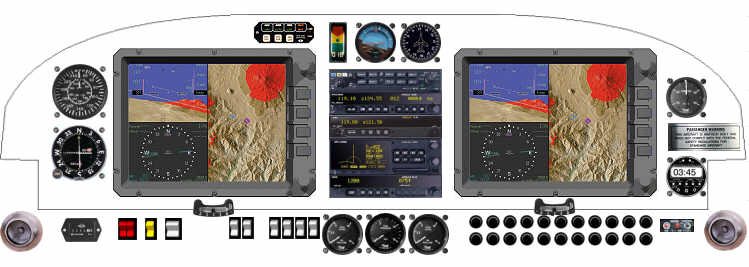
Up until this point, I think we were still waiting for our quickbuild to show up. I can’t remember for sure, but when we got to the point of fitting the front fuselage area, we got to thinking about the structure behind the panel… Stuff you never see. Out of sight, out of mind right? Looking at other sites, it was clear that storage was an issue. At this point, it was time for a rethink to accommodate storage, structure and let’s not forget er.. Budget… We’ve already blown that! Better shrink the stack a tad too….
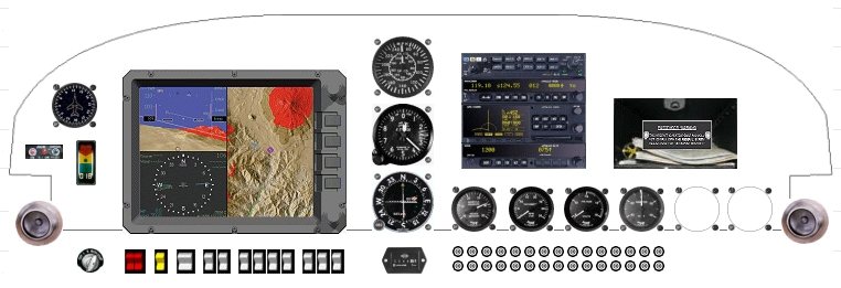
We’re getting a little closer to the final design. I’d been reading about people having trouble getting their compass to work properly when it was buried in the panel, so I decided to relocate it to the windshield area. After all, the support bar for the slider is stainless steel for just this reason! Heaven knows why I put all those circuit breakers along the bottom right! It would be a miracle if you could stack them up like this. I’m not even using breakers. I’m going with the AeroElectric suggested standard fuseblocks. I’ll have a couple of breakers for alternator fields, but that’s it. This plane will be all electric, dual alternator per Bob’s Z-10 schematic.
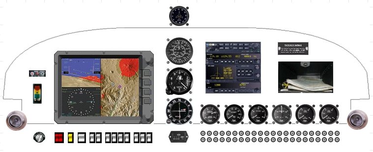
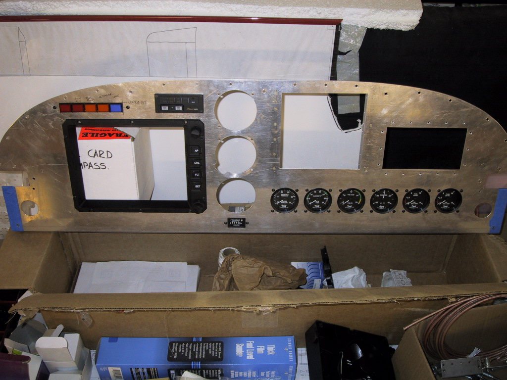
So, here we have what closely resembles our final design. The only thing missing here are warning lamps. Trim indicators, will be positioned on the centre console by the quadrant, and the ELT remote panel has been positioned of to the side of the panel in the side rail just under the canopy roll bar. There’s a picture further down showing this. After much debate, I decided that we need a gyro of some kind if the lights go out in IMC. So, now there’s an electric AI (with internal battery backup) for just such circumstance. Most recently, it was decided to ditch the CDI. The EFIS1 displays all the information we need these days from internal sources, and multiple external sources. Now we can move the AOA Pro up to a better locale.
Also, after much pain with searching for rocker switches that fitted the bill perfectly, and consistently, I gave up and went for the toggles. Further on you’ll see how I made them look nicer.
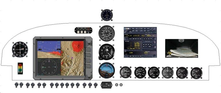
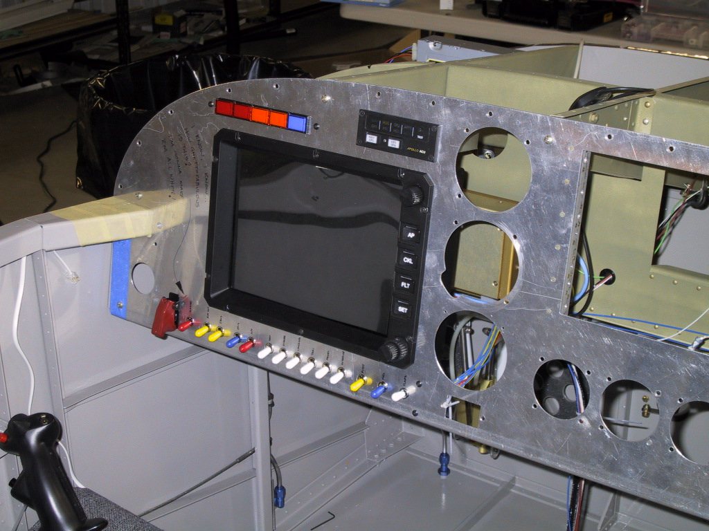
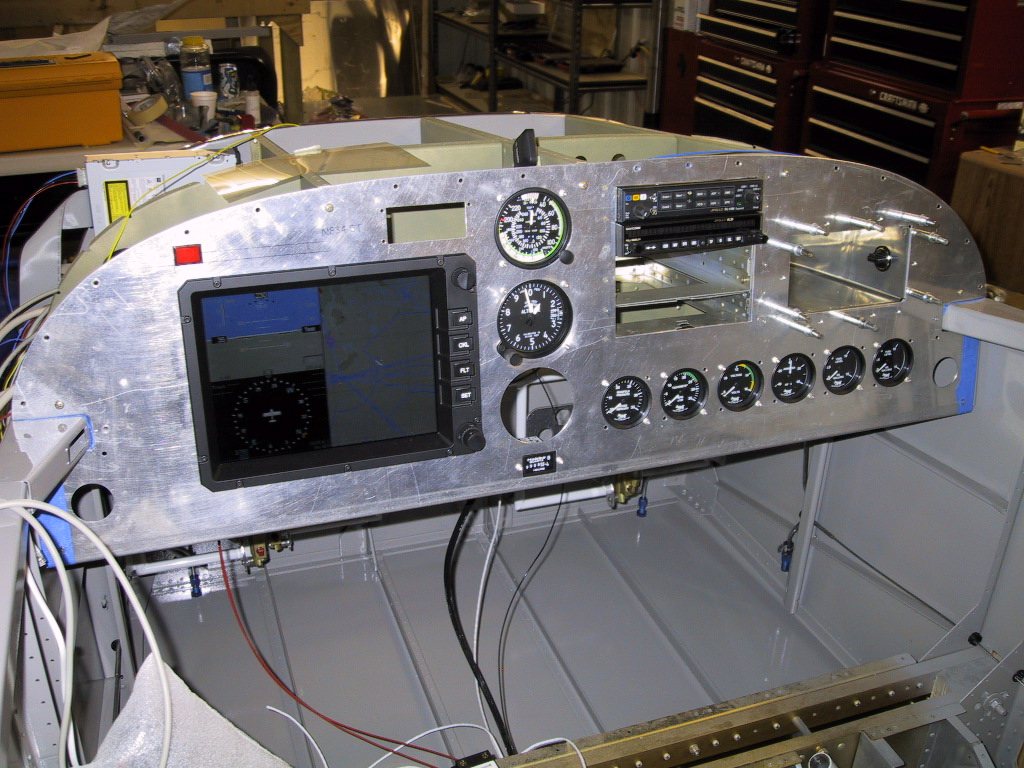
Ah ha… There’s that EFIS1! As you probably guessed everything had to make way for this! Looking good though. Here, it was fired up to give some of the local pilots a demo. Everyone was suitably impressed, as they should be!
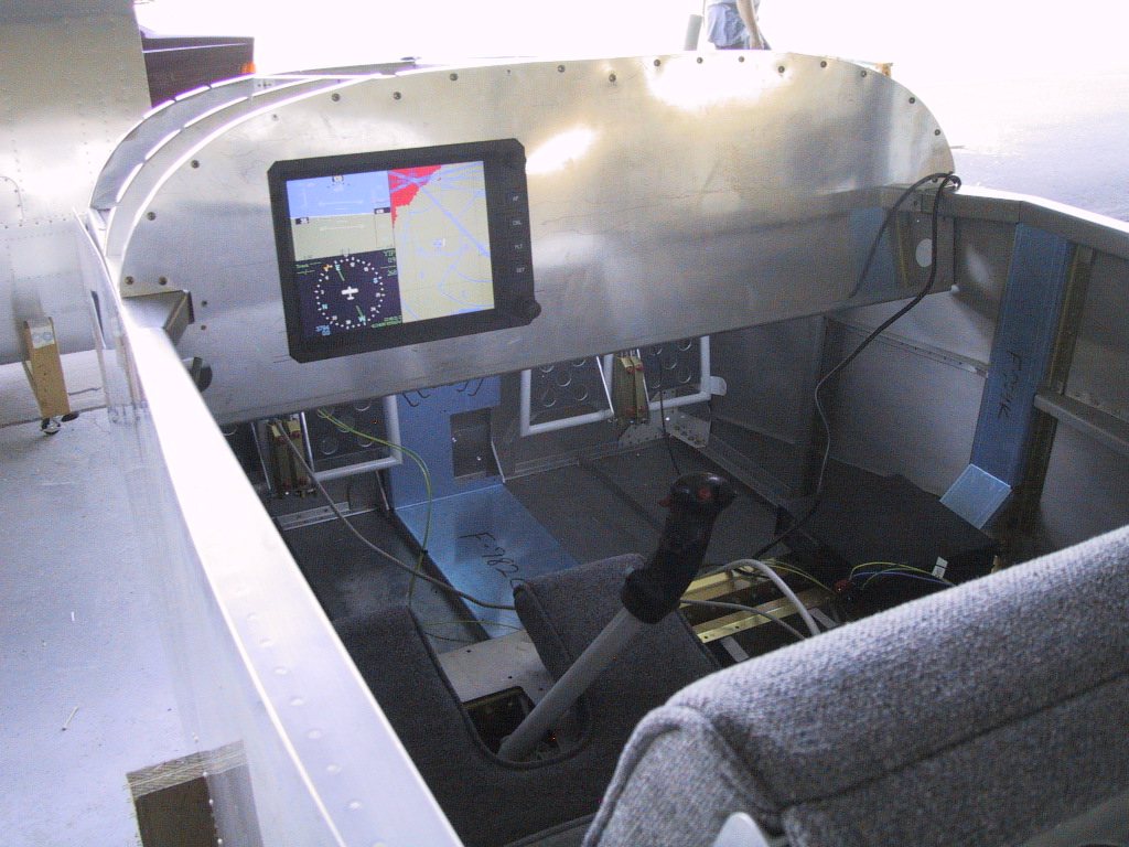
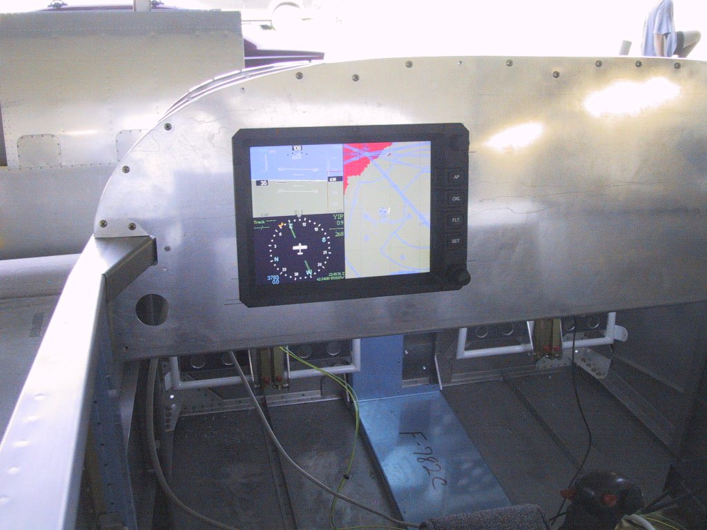
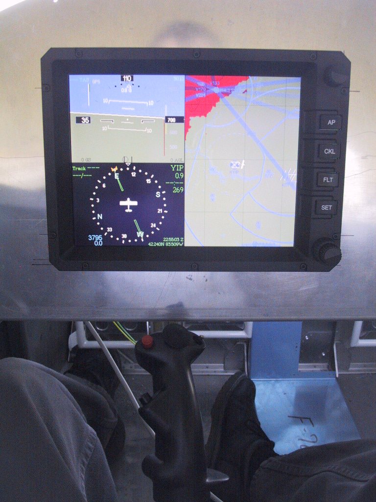
Mucking about with paper templates. This effort didn’t get very far….
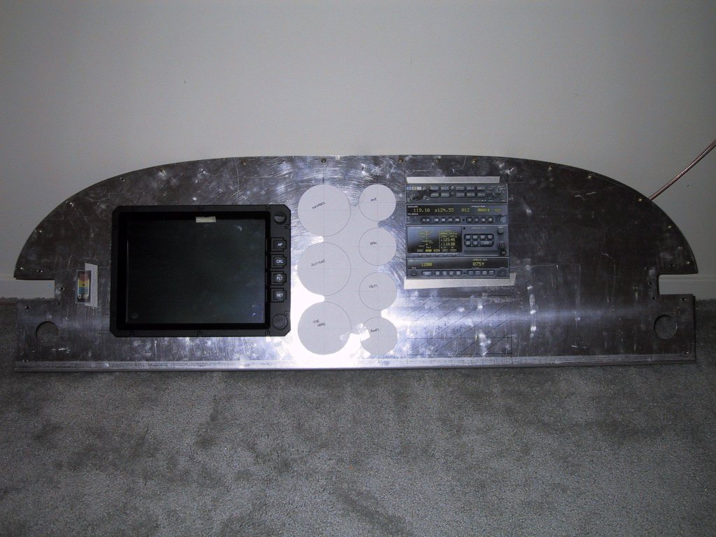
Before we knew it, metal was cut! So much for make your mistakes on paper!
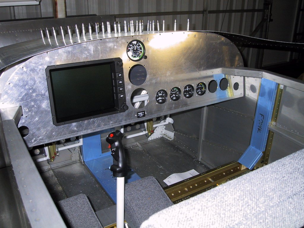
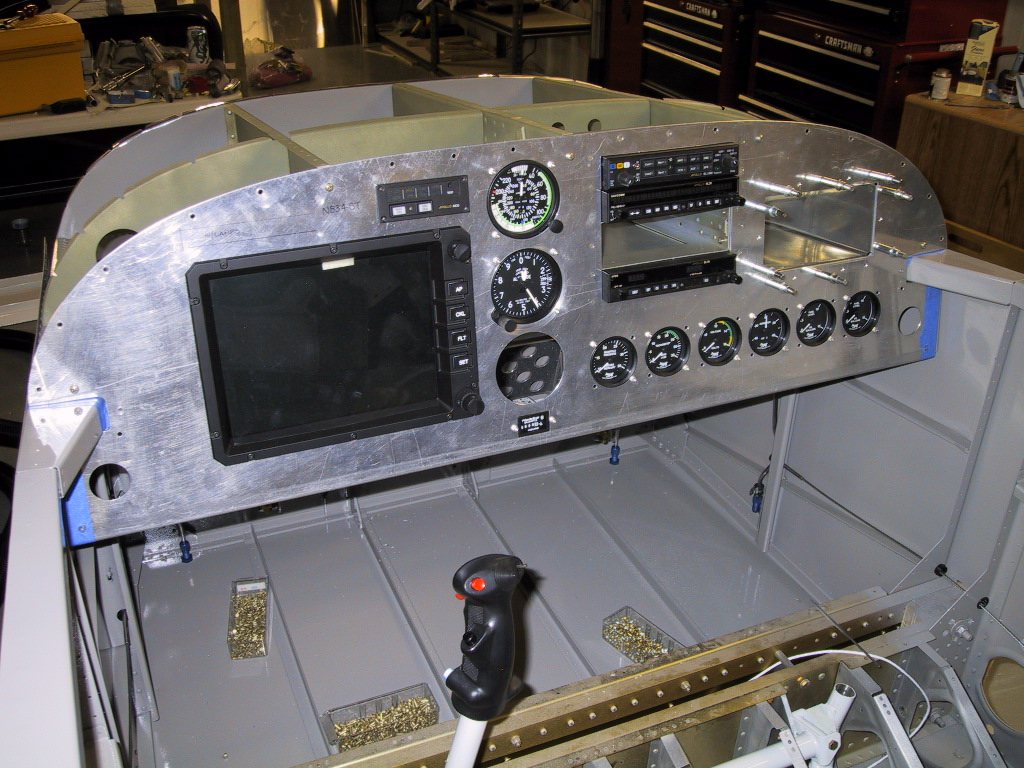
This is a good shot showing the extra panel depth. I added 2". In order to do this, I had to trim quite a bit off the control stick. There’s still plenty of leverage though. These things don’t take that much force to fly!
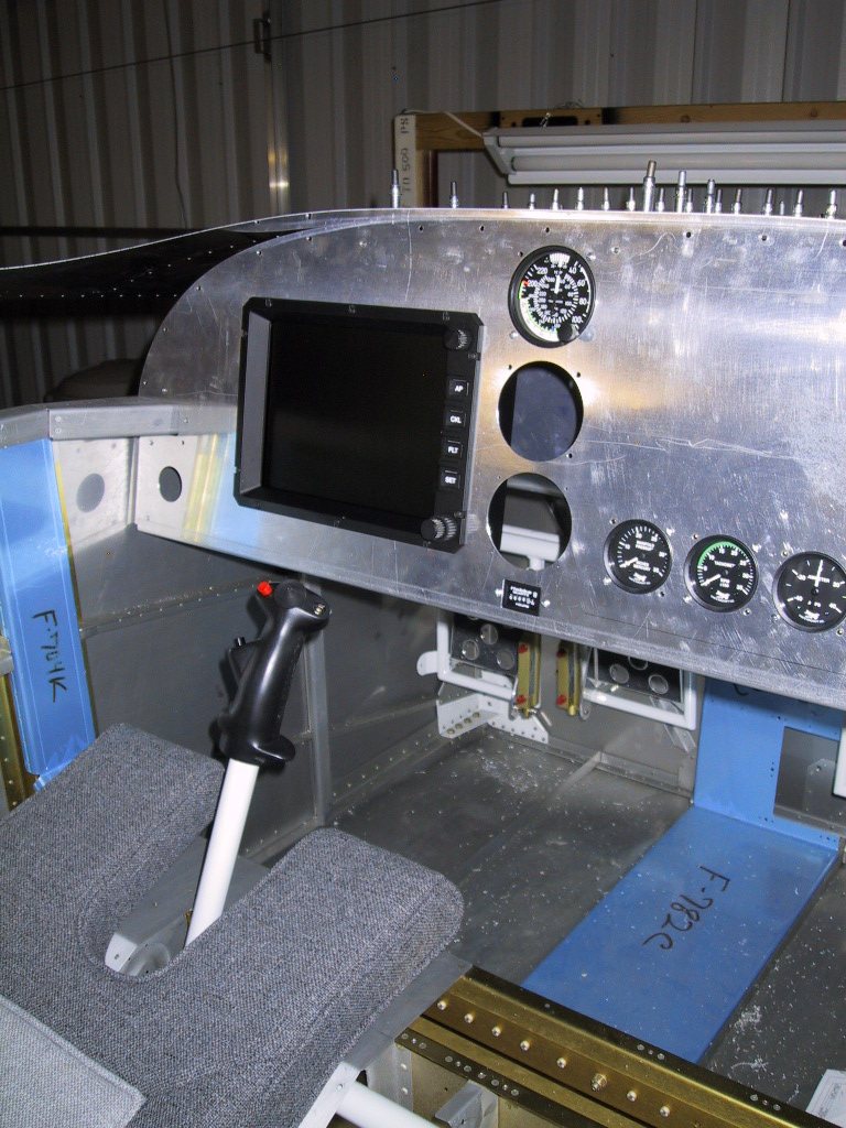
At this point, the radio stack is still made out of paper… Money, money, money….. MONEY (Sang like The Apprentice theme tune.)
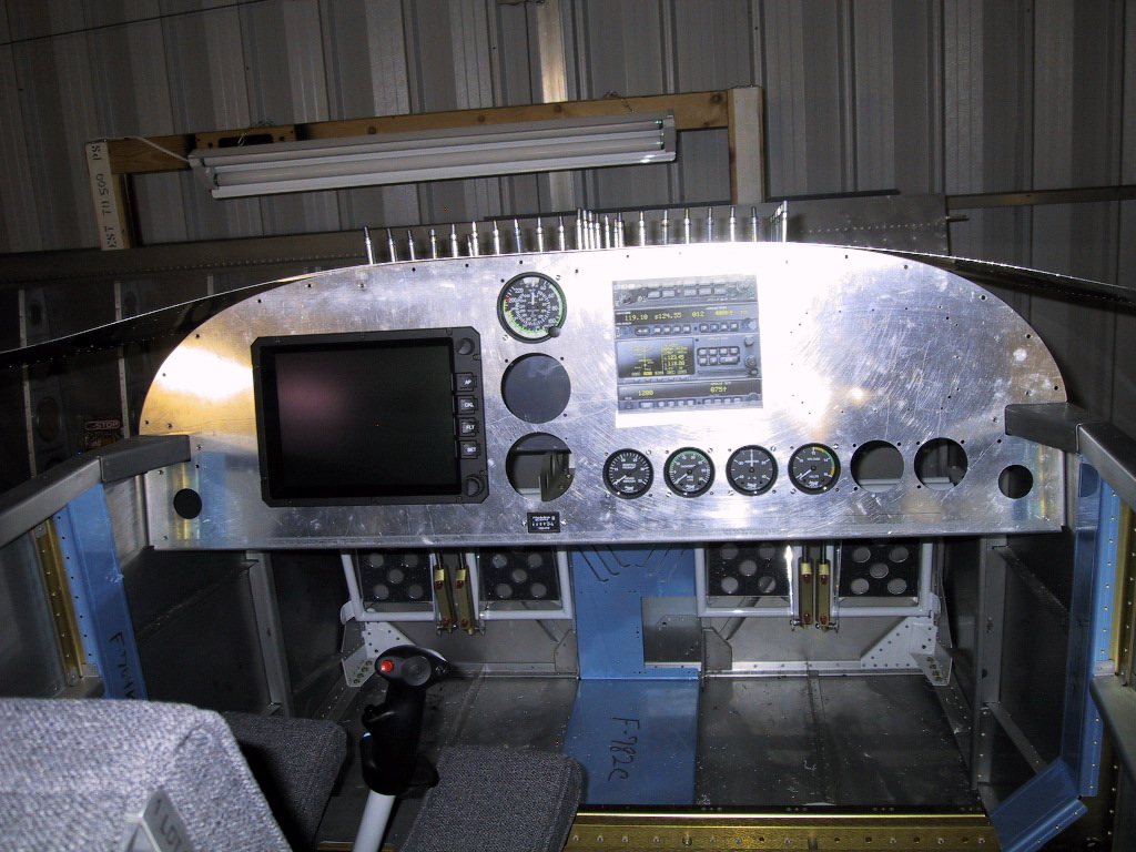
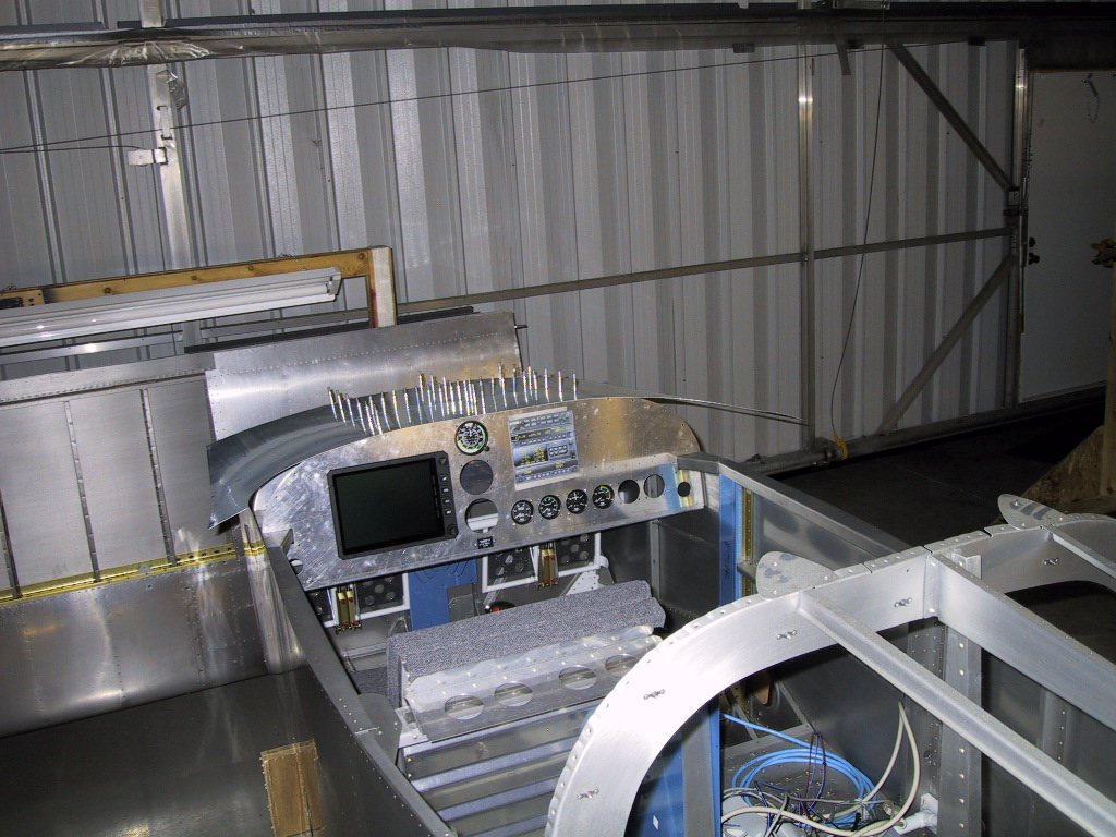
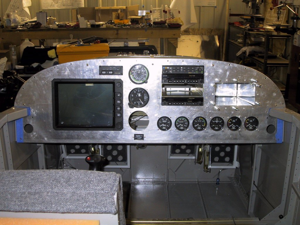
Got the glove box kit from Van’s… Let’s see how we can work this into the design… Hmmm Perfect! It looks almost planned!
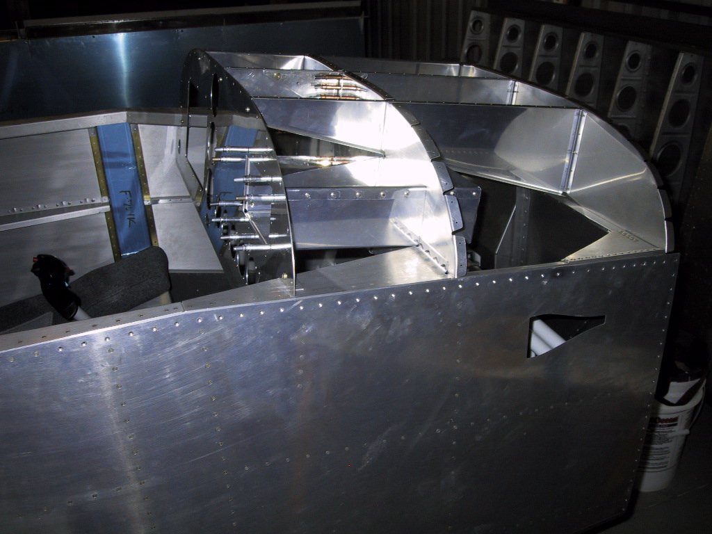
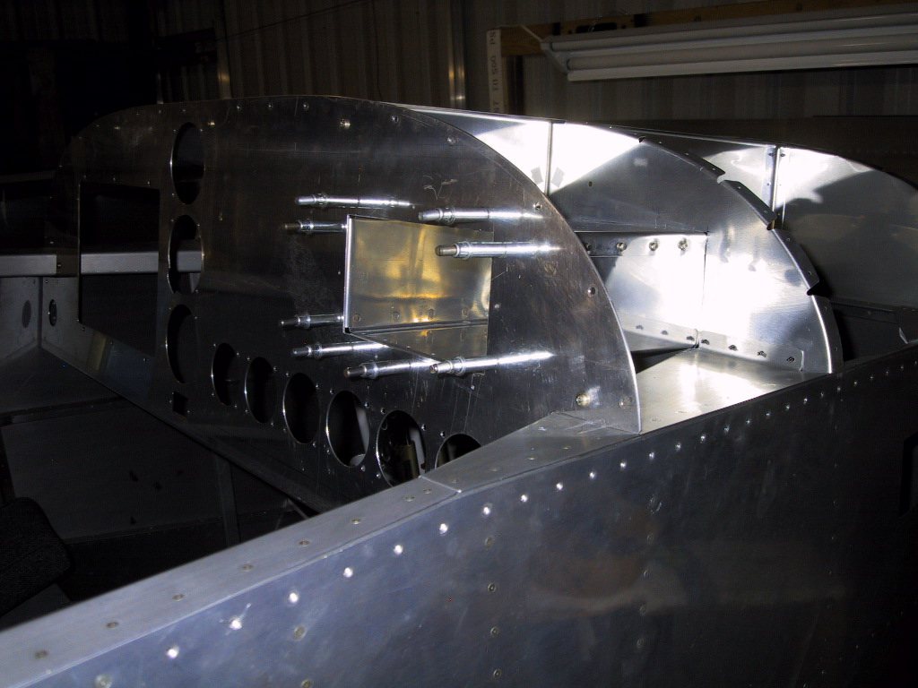
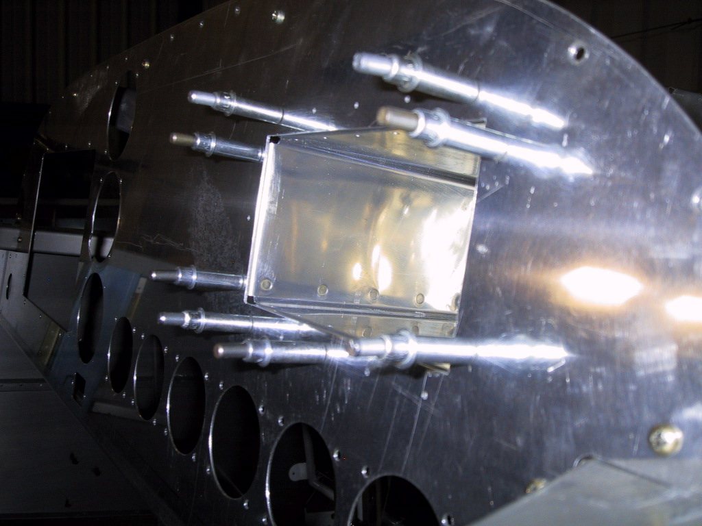
Still no radios. The paper ones finally gave up the ghost and fell off. That’s be my cue to get some real ones.
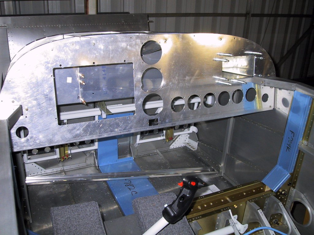
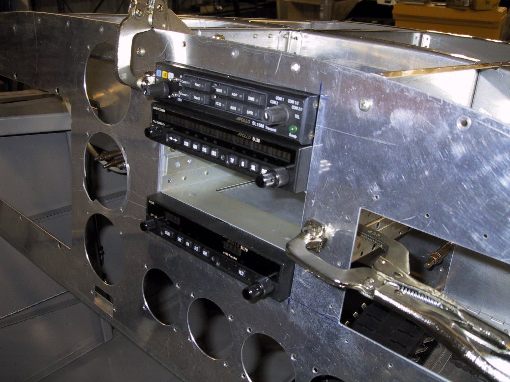
Hey, hey! Here they are. I’ve been looking at this stuff forever, and finally got them. I was going through my Internet Explorer Favourites one day looking for dead links, and stumbled upon the Barnstormers one… I clicked it, and out of the blue I typed in the search feature the word ‘Apollo’… Was this an omen? There it was… Amazing. This stuff comes up for sale so rarely on the used market, I had to have it. One phone call, and it was secured. Well, maybe not one phone call. The first call was to see if it was even still available. It was…. Now a dilemma. Always a member of the ‘forgiveness is easier to get than permission’ camp, I pondered… Should I just go ahead and get it? After all, this stuff doesn’t come up every day, and it’s a reasonable price over new stuff, and Garmin have taken over, how long will it be available new? Mind is racing even writing about it after the fact! I broke down and deviated from my normal habit and called the wife. She wasn’t there. Leave a loving message, hi darling, blah, blah… Love you, bye. Didn’t hear from her all day. Got home, put it to her and she of course says, “NO!” She made me beg and plead…. She knew she was in complete control, and was lapping up every bit of it. The next day over breakfast, she said, “So, what about these radios then?” I said, In a mardy tone, “I guess I’ll just miss out and spend more later.” About a half hour later, she told me to go ahead and buy the radios! Woo hoo! See what we have to do to get what we want? Next time, I’m going the forgiveness route for sure!
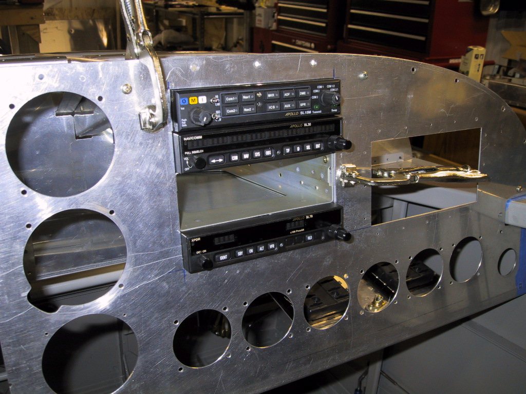
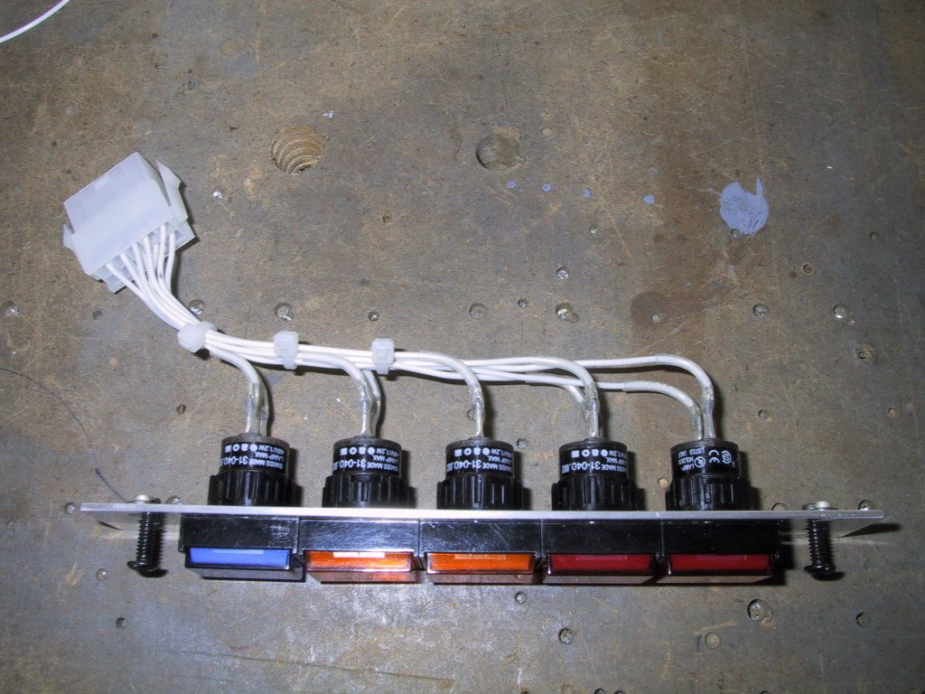
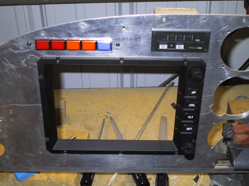
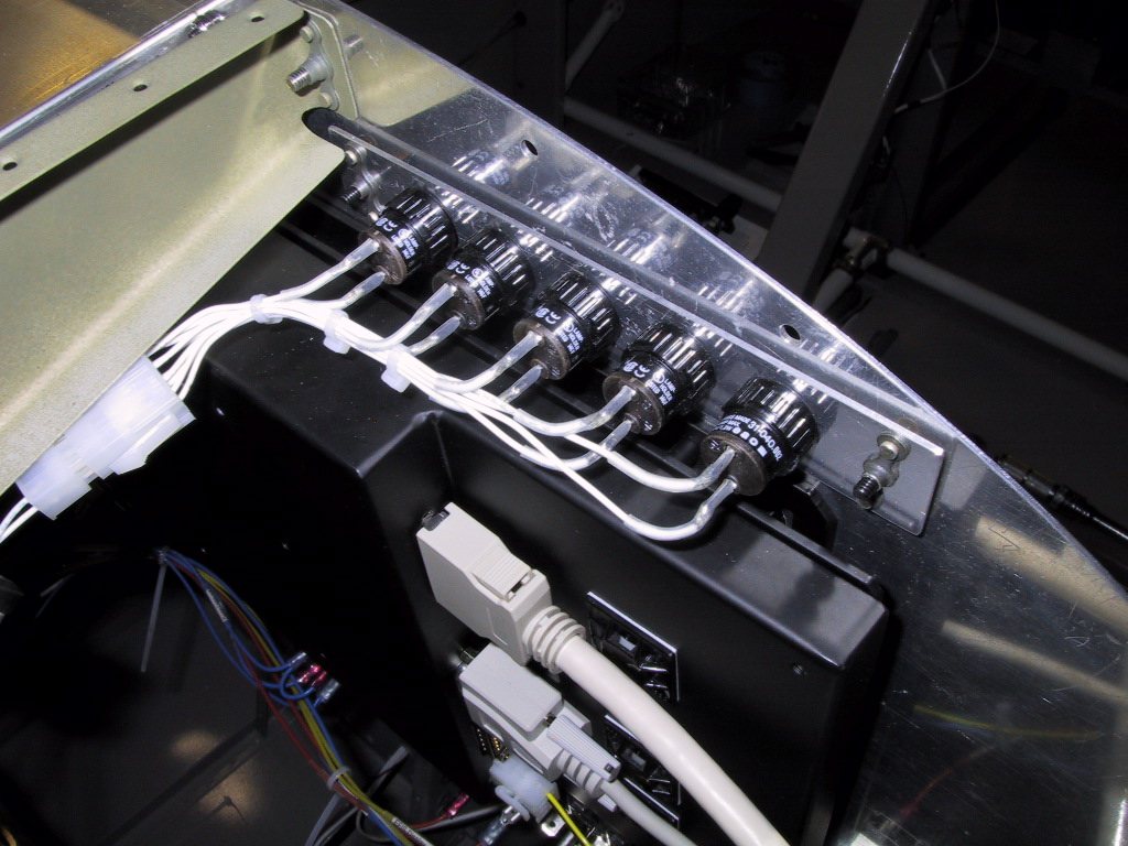
These warning lamps came from Spruce. They’re quite pricey though at $12 a pop. I mounted them to a support strip of aluminium, and stood it back behind the panel so the lamps were lower profile. They look a lot neater and more professional like this. The lens caps can be removed, and there’s a secondary opaque lens cap underneath onto which you can put a clear label. Then snap the coloured cover back on and you have a great looking finish.
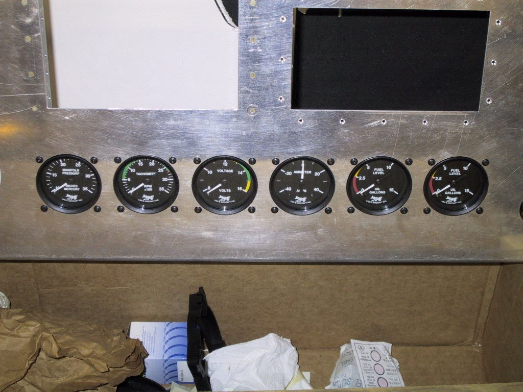
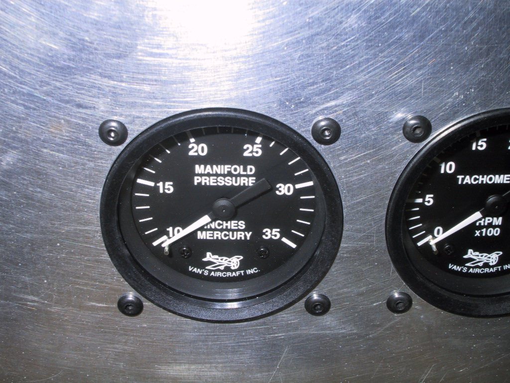
I found some nice dome head hex socket screws for the instruments, but I’m having some trouble finding longer lengths than half an inch! I’ll keep looking. These came from McMaster-Carr.
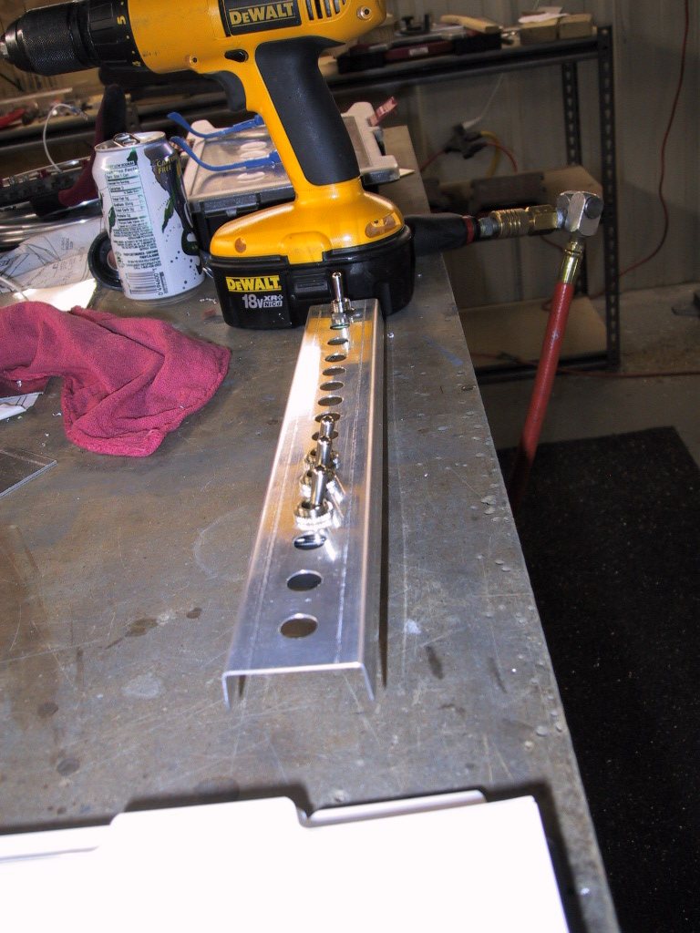
Here you can see the switches. Lot’s of them. I made a channel out of 0.040" aluminium which hold the switches, which in turn mounts to the panel. The top of the threads on the switches sits flush with the panel. Looks much nicer than having all those lock nuts on display. The problems with the lock nuts I’ve noticed is that you cannot orient them the same way too well. Especially if you have some slightly different types of switch with different threads.
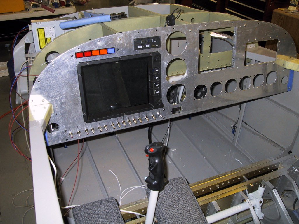
Here you can see the standoff panel attached to the panel.
This shows the standoff channel for the switches. Since these are pushed and prodded everytime you fly, it had to be stiff. It’s made from 0.040" sheet, and is plenty stiff enough.
Here, it’s all attached to the panel. In the foreground is the Hobbs meter. The black thing above the switches is the EFIS1 display. Snug in there isn’t it?! I haven’t pushed on any of the terminals fully yet. I don’t want to work it all loose by pulling them off several times before it’s all sorted.
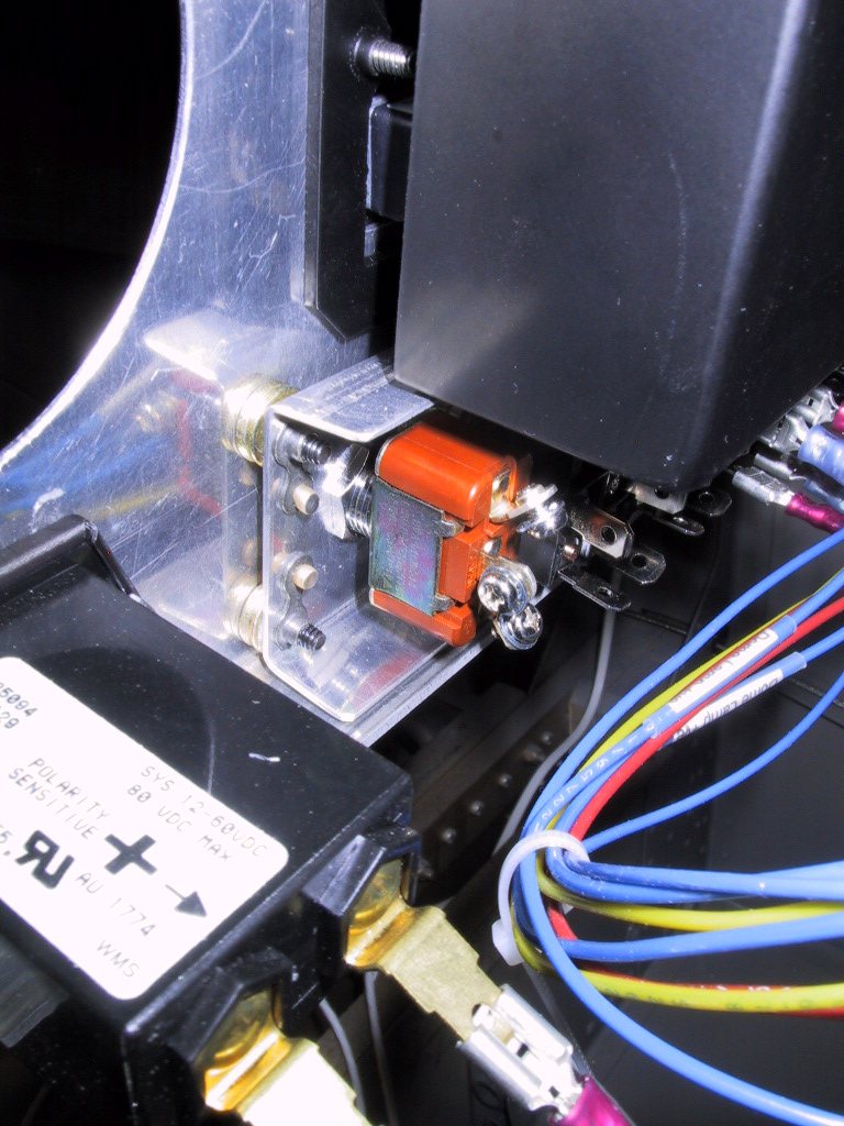
Another shot of the switch array.
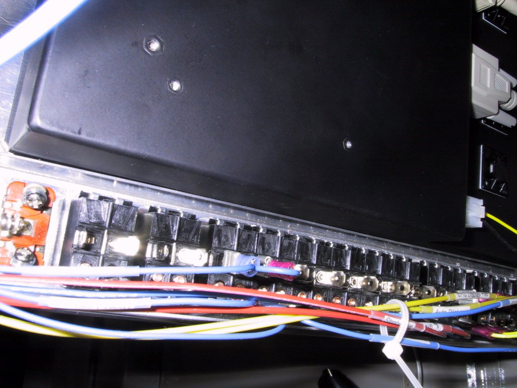
Here I let the switches try on their new booties. However, my feeling is after trying them on is that they look like christmas tree lights. Not good. So, I’ll be changing them all out to be white, except for the important stuff like the master , autopilot master and E-Bus alt feed switches, which will be red. I thought it’d be a good idea to have them all coloured in, but maybe I ‘smoked too much crack’ as Cameron would say. A word of caution… If you have some booties like this, don’t get impatient like me and put them on before you’re ready. They don’t come off too easily!
The flip cover is over the starter switch. The real starter switch will be on the stick, but this switch must be turned on in order to use the switch on the stick. Basically a safety lockout to stop you hitting the starter button in turbulence for example.